
Light spot position detection sensor

A technology for detecting sensors and light spots, applied in the field of sensors, can solve problems such as increased manufacturing costs, and achieve the effects of increased sensitivity, reduced manufacturing costs, and low material costs

Inactive Publication Date: 2012-07-04
SOUTHEAST UNIV
View PDF3 Cites 8 Cited by
  • Summary
  • Abstract
  • Description
  • Claims
  • Application Information

AI Technical Summary

Problems solved by technology

Although the use of PIN structure to realize light spot position detection has the aforementioned advantages such as high detection sensitivity, but because it involves the use of a near-intrinsic I-layer material layer, the manufacturing cost is greatly increased.

Method used


Image

  • Light spot position detection sensor
  • Light spot position detection sensor
  • Light spot position detection sensor

Examples


Embodiment Construction

[0019] In order to make the technical means, creative features, goals and effects achieved by the present invention easy to understand, the present invention will be further described below in conjunction with specific embodiments.

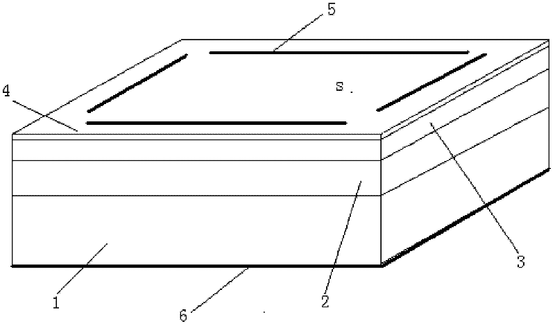
[0020] see figure 1 , the present invention includes a first low-resistance semiconductor layer 1 (highly doped), a high-resistance semiconductor layer 2, a second low-resistance semiconductor layer 3 and an insulating anti-reflection protective layer 4 arranged in sequence from bottom to top, wherein the insulating anti-reflection The protective layer 4 is a transparent layer.

[0021] Wherein, the first low-resistance semiconductor layer 1, the high-resistance semiconductor layer 2, and the second low-resistance semiconductor layer 3 are all semiconductor materials, such as ordinary silicon wafers, which can significantly reduce the manufacturing cost of the present invention.

[0022] The conductivity type of the first low-resistance semicondu...


PUM


Abstract

The invention discloses a light spot position detection sensor. The light spot position detection sensor comprises a first low-resistance semiconductor layer, a high-resistance semiconductor layer, a second low-resistance semiconductor layer and an insulating anti-reflection protection layer, wherein the first low-resistance semiconductor layer, the high-resistance semiconductor layer, the second low-resistance semiconductor layer and the insulating anti-reflection protection layer are arranged successively, the first low-resistance semiconductor layer and the high-resistance semiconductor layer are of the same conducting type; the second low-resistance semiconductor layer and the high-resistance semiconductor layer are of reverse conducting types, so that a semiconductor PN junction is formed; the doping concentration of the second low-resistance semiconductor layer is higher than the doping concentration of the high-resistance semiconductor layer; the surface of the insulating anti-reflection protection layer is provided with four same electrodes; the four electrodes define a square effective photosensitive area; and the surface of the first low-resistance semiconductor layer is provided with a metal layer. The light spot position detection sensor works on the basis of an avalanche breakdown principle, response current has a self-activation amplification function, and the sensitivity is greatly increased; and the light spot position detection sensor can be manufactured with an ordinary silicon wafer, so that the material cost is low, and the manufacturing cost of the sensor is lowered remarkably.

Description

technical field [0001] The invention relates to a sensor, in particular to a light spot position detection sensor. Background technique [0002] Optical point position detection sensors are widely used in the fields of optical position and angle measurement and control, remote optical control systems, displacement and vibration monitoring, laser beam calibration, automatic range detection systems, and human motion and analysis systems. [0003] The traditional light point position detection sensor is made on silicon material and consists of a large area PIN photodiode. Compared with the discrete unit detector array, it has the advantages of high position resolution, simple and fast response current, etc. [0004] In recent years, there are also reports on the manufacture of PIN-type optical point position detection sensors on SOI substrate silicon. Although adopting the PIN structure to realize light spot position detection has the aforementioned advantages such as high det...

Claims


Application Information

Patent Timeline
IPC IPC(8): H01L31/107H01L31/068G01B7/004
CPCY02E10/50Y02E10/547
Inventor 秦明张睿
Owner SOUTHEAST UNIV
Learn More