Eureka AIR delivers breakthrough ideas for toughest innovation challenges, trusted by R&D personnel around the world.

Phase change memory and preparation method thereof

A technology of phase-change memory and memory, which is applied in the direction of semiconductor devices, electric solid-state devices, electrical components, etc., to achieve the effect of reducing leakage current and increasing current efficiency

Active Publication Date: 2014-02-05
SEMICONDUCTOR MANUFACTURING INTERNATIONAL (BEIJING) CORP
View PDF4 Cites 0 Cited by
  • Summary
  • Abstract
  • Description
  • Claims
  • Application Information

AI Technical Summary

Problems solved by technology

The vertical diodes in the prior art are silicon PN junction diodes, so it is inevitable that the carrier leakage current caused by the electric field will be generated at the PN junction

Method used


Image

  • Phase change memory and preparation method thereof
  • Phase change memory and preparation method thereof
  • Phase change memory and preparation method thereof

Examples


Embodiment Construction

[0068] In order to make the above objects, features and advantages of the present invention more comprehensible, specific implementations of the present invention will be described in detail below in conjunction with the accompanying drawings.

[0069] In the following description, many specific details are set forth in order to fully understand the present invention, but the present invention can also be implemented in other ways than those described here, so the present invention is not limited by the specific embodiments disclosed below.

[0070] As mentioned in the background technology section, the peripheral circuit area cannot work well in the preparation of phase-change memory in the prior art, and the silicon PN junction diode will inevitably generate carrier leakage current caused by the electric field at the PN junction , which is not conducive to the realization of high density and low energy consumption of the phase change memory.

[0071] Therefore, in the prepar...


PUM


Abstract

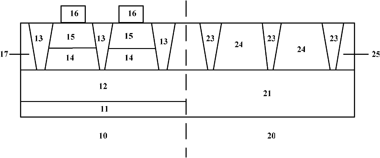
The invention provides a phase change memory and a method for forming the phase change memory. The phase change memory includes a storage region and a peripheral circuit region. The peripheral circuit region has a peripheral substrate, peripheral shallow trench isolation (STI) units in the peripheral substrate, and MOS transistors on the peripheral substrate and between the peripheral STI units. The storage region has a storage substrate, an N-type ion buried layer on the storage substrate, vertical LEDs on the on the N-type ion buried layer, storage shallow trench isolation (STI) units between the vertical LEDs, and phase change layers on the vertical LEDs and between the storage STI units. The storage STI units have thickness equal to thickness of the vertical LEDs. Each vertical LED comprises an N-type conductive region on the N-type ion buried layer, and a P-type conductive region on the N-type conductive region. The P-type conductive region contains SiGe. The peripheral STI units have thickness equal to thickness of the storage STI units. A top of P-type conductive region is flush with a top of the peripheral substrate. The P-type conductive region containing SiGe reduces drain current through the vertical LED and raises current efficiency of the vertical LED. The peripheral circuit region can work normally without adverse influence on performance of the phase change memory.

Description

technical field [0001] The invention relates to a device in the technical field of semiconductors and a preparation method thereof, in particular to a phase change memory and a preparation method thereof. Background technique [0002] Recently, a phase change random access memory (Phase Change RAM, PCRAM) device (referred to as a phase change memory) has been proposed as a nonvolatile semiconductor memory device. A unit storage unit of a phase change memory uses a phase change material as a data storage medium. A phase change material has two stable phases (for example: amorphous phase and crystalline phase) depending on the heat supplied to it. Known phase change materials are Ge—Sb—Te (GST) compound, which is a mixture of germanium (Ge), antimony (Sb), and tellurium (Te), among others. Heat is supplied to effect a phase change in the phase change material. [0003] If the phase change material is heated for a short time at a temperature close to its melting temperature ...

Claims


Application Information

Patent Timeline
Patent Type & Authority Patents(China)
IPC IPC(8): H01L45/00
CPCH01L45/144H01L45/06H01L27/24H01L27/15H01L45/1213H10B63/00H10N70/257H10N70/231H10N70/8828
Inventor 三重野文健何有丰
Owner SEMICONDUCTOR MANUFACTURING INTERNATIONAL (BEIJING) CORP
Why Eureka
Eureka Blog
Learn More