Multimode resonant antenna system
An antenna system, multi-mode resonance technology, applied to antennas, antenna supports/mounting devices, devices that enable antennas to work in different bands at the same time, can solve the problem of antenna failure, clearance area, and antenna design that cannot meet the PCB board And other issues
- Summary
- Abstract
- Description
- Claims
- Application Information
AI Technical Summary
Problems solved by technology
Method used
Image

Examples
Embodiment 1
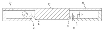
[0097] figure 1 It is a schematic diagram of the principle of the antenna of the first embodiment of the present invention. refer to figure 1 , the antenna includes a feed end 24 , a ground end 25 , and an antenna main body; the antenna main body includes a first part 23 , a second part 22 and a third part 21 .
[0098] The first part 23 and the third part 21 are structurally symmetrical, and the first part 23 and the third part 21 are coupled to the second part 22 with a gap of a certain distance g.
[0099] Both the first part 23 and the third part 21 are composed of several radiation units with different widths / lengths. Such a structure enables the antenna system to simultaneously cover multiple frequency bands such as low frequency and high frequency.
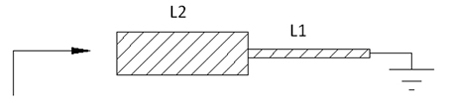
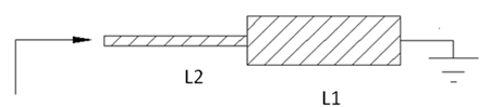
[0100] The following theory deduces the frequency characteristics brought about by this structure:
[0101] refer to Figure 2a , two basic resonant units of multimode antennas with different lengths and widths, among ...
Embodiment 2
[0130] Figure 10 It is a schematic structural diagram of the antenna system according to the second embodiment of the present invention. As shown in FIG. 2 , a multi-mode resonant antenna system includes an antenna 200 and a PCB 100 , the antenna 200 is disposed above the PCB 100 , and the projected area of the antenna 200 on the PCB 100 is a metal area.
[0131] Line A and line B are two vertical centerlines of the PCB board respectively.
[0132] The antenna 200 further includes: an antenna body, a feeding terminal 202 and a ground terminal 201 ; the antenna 200 is connected to the PCB board 100 through the ground terminal 201 .
[0133] The antenna body further includes a first part, a second part and a third part; the first part is connected to the third part through the second part; the first part is connected to the feeding terminal 202, and the third part is connected to the ground terminal 201 ; The first part and the third part are symmetrical; the feeding end 20...
Embodiment 3
[0143] Figure 11 It is a schematic structural diagram of the antenna system according to the third embodiment of the present invention. Such as Figure 11 , a multi-mode resonant antenna system includes an antenna 200 and a PCB board 100, and the antenna 200 is arranged above the PCB board 100.
[0144] The projection area of the antenna 200 on the PCB 100 is a metal area.
[0145]Antenna 200 further includes: antenna main body, feeding end 202 and grounding end 201; Antenna 200 is connected with PCB board 100 through grounding end 201; Antenna main body further includes a first part, a second part and a third part; The two parts are connected to the third part; the first part is connected to the feeding end 202 , and the third part is connected to the grounding end 201 .
[0146] Line A and line B are two vertical centerlines of the PCB board respectively.
[0147] The second part is a concave structure, which includes the first radiation unit 1, the second radiation u...
PUM
 Abstract
Description
Claims
Application Information
PatSnap Eureka turns technology decisions into work you can execute. Powered by our Innovation Knowledge Graph, it runs expert workflows across engineering, life sciences, materials and intellectual property. Get your review-ready output in minutes.


