Permanent magnet direct-driven vernier motor

A vernier motor, direct-drive technology, applied to synchronous motors with stationary armatures and rotating magnets, magnetic circuit shape/style/structure, magnetic circuit static parts, etc., can solve the problem of large magnetic flux leakage and core loss , Difficult processing technology, limited power density and other problems, to achieve the effect of increasing output torque, compact structure and reducing volume

Inactive Publication Date: 2012-07-04
SOUTHEAST UNIV
View PDF5 Cites 7 Cited by
  • Summary
  • Abstract
  • Description
  • Claims
  • Application Information

AI Technical Summary

Problems solved by technology

Although there is one less air gap than the traditional direct-drive motor with three air gaps, the structure is still more complicated and the processing technology is more difficult
Large flux leakage and core loss, limited power density

Method used


Image

  • Permanent magnet direct-driven vernier motor
  • Permanent magnet direct-driven vernier motor
  • Permanent magnet direct-driven vernier motor

Examples


Embodiment Construction

[0013] The technical solution of the present invention will be described in detail below in conjunction with the accompanying drawings.

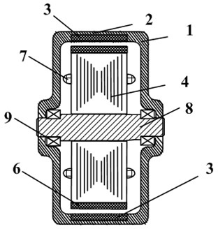
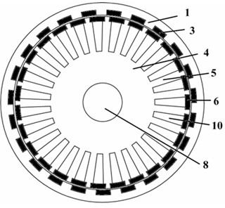
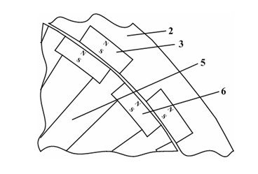
[0014] Such as Figure 1 to Figure 3 As shown, a permanent magnet direct drive vernier motor of the present invention includes an outer rotor 1 , an outer rotor permanent magnet 3 , a stator 4 , a stator permanent magnet 6 , a winding 7 , a motor shaft 8 and a bearing 9 . The outer rotor 1 is located outside the stator 4 . That is, the stator 4 is located inside the outer rotor 1 . The outer rotor 1 is rotatably connected to the motor shaft 8 through a bearing 9 . The bearing 9 is fixed on the inside of the outer rotor 1 , and the two ends of the motor shaft 8 are respectively located in one bearing 9 , and the outer rotor 1 can rotate around the motor shaft 8 . The motor shaft 8 is fixedly connected with the stator 4 . Since the motor shaft 8 is fixedly connected to the stator 4 , the outer rotor 1 can rotate around the stator 4 . The ...


PUM


Abstract

The invention discloses a permanent magnet direct-driven vernier motor which comprises an outer rotor, an outer rotor permanent magnet, a stator, a stator permanent magnet, windings, a motor shaft and a bearing, wherein the outer rotor is rotatably connected with the motor shaft through the bearing, the motor shaft is fixedly connected with the stator; the outer rotor permanent magnet is embedded in a rotor yoke; the stator is provided with stator teeth along the circumference, two sides of the top of the stator teeth are respectively provided with notches, a stator slot is formed between the adjacent two stator teeth; the windings are wound on the stator teeth; the end face of the stator permanent magnet is embedded in the notch of the adjacent two stator teeth; the stator permanent magnet and the outer rotor permanent magnet adopt radial magnetization, and the magnetization directions of the stator permanent magnet and the outer rotor permanent magnet are same; clearances are reserved between the stator permanent magnet and the outer rotor, as well as the stator teeth and the outer rotor, and the sum of the number of pole pairs (nr) of the outer rotor permanent magnet and the number of pole pairs (np) of the windings is the number (ns) of the stator teeth. The motor has simplified components and compact structure and can reduce the magnetic flux leakage and improve the motor efficiency.

Description

technical field [0001] The invention relates to a vernier motor, in particular to a permanent magnet direct drive vernier motor, which is especially used in a low-speed and high-torque environment. Background technique [0002] In order to avoid problems such as high noise, low efficiency, low transmission accuracy, slow response, and mechanical wear of mechanical gear transmission systems in industrial production, direct drive motors are often used. However, in order to obtain low-speed and high-torque output, traditional direct-drive motors are generally bulky and costly. The traditional direct drive motor mainly includes the outer rotor of the magnetic gear, the magnetic ring, the inner rotor of the magnetic gear and the motor stator. There is an air gap between the outer rotor of the magnetic gear and the inner rotor of the magnetic gear. There is also a layer of air gap between the motor stator and the inner rotor of the magnetic gear, and there are three layers of air...

Claims


Application Information

Patent Timeline
Patent Type & Authority Applications(China)
IPC IPC(8): H02K21/22H02K1/17H02K1/27
Inventor 樊英金小香黄进罗勇
Owner SOUTHEAST UNIV
Why Eureka
Try Eureka