
Method for inspecting corrosion under insulation
A technology of insulating layer and rms value, which is applied in the field of corrosion under the insulating layer in inspection equipment, can solve problems such as poor efficiency and achieve low-cost effects
Patent Information
- Authority / Receiving Office
- CN · China
- Patent Type
- Applications(China)
- Current Assignee / Owner
- Publication Date
- 2012-07-04
- Estimated Expiration
- Not applicable · inactive patent
Smart Images
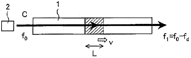
Figure 1 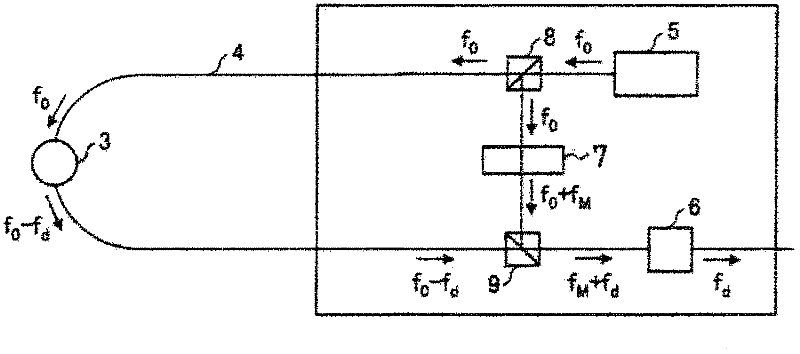
Figure 2 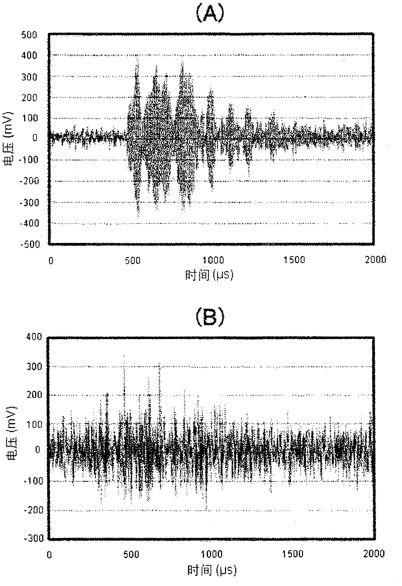
Figure 3
Abstract
Description
technical field
[0001] The invention relates to a method for inspecting corrosion under insulation in equipment. In particular, the present invention relates to a method for under-insulation inspection that enables simple and precise inspection of said corrosion in insulation-covered equipment at relatively low cost. Background technique
[0002] Since corrosion under insulation is a major cause of leakage failures in equipment made of carbon steel or low alloy steel, corrosion under insulation is one of the severe degradation phenomena monitored in chemical plants that have been in operation for many years.
[0003] Typically, in chemical plants and the like, many pieces of equipment such as towers and vessels, valves and plugs, and heat exchangers are covered with insulation.
[0004] The insulation needs to be removed in order to visually inspect corrosion under insulation (hereinafter referred to as "CUI"). Furthermore, when scaffolding is erected in order to dismantle...
Examples
example 1
[0092] The insulating layer was removed from the air oxidation reactor (3.8 m in inner diameter) in which the liquid moved, and 4 FOD sensors (ch1 to ch4) were attached at intervals of 90° in the circumferential direction. The coating on the outer surface was removed with sandpaper, the FOD sensor was attached to the outer surface using a heat resistant epoxy based adhesive, and the FOD sensor was secured with aluminum tape attached to the FOD sensor.
[0093] Corrosion with an area of about 320 mm x about 90 mm and a depth of about 0.3 mm to about 0.5 mm was found at about 2.5 m above the FOD sensor ch1. No corrosion was found within 4m from the FOD sensor ch2. Corrosion with an area of about 350 mm x about 65 mm and a depth of about 0.3 mm to about 1.0 mm was found at about 2.5 m above the FOD sensor ch3, and at a position about 2 m from the lower right of the FOD sensor ch3 with an area of Corrosion of about 720mm by about 110mm, with a depth of about 0.3mm to 0.6mm. ...
example 2
[0108] Such as Figure 9 A model piping system was prepared as shown.
[0109] An insulating layer 13 was attached to a carbon steel pipe 10 having a total length of 5 m, and silicon oil heated by a heater 12 was circulated in the pipe 10 . In addition, corrosion is artificially accelerated in order to efficiently produce CUI. Specifically, pure water is continuously dripped from the dripping device 11 to the surface of the pipe 10, and the amount of the dripping liquid is finely adjusted to alternately produce a wet state and a dry state. Besides, common salt is coated on the surface of the pipe 10 . In addition, the silicone oil circulating through the pipe 10 is heated to a temperature in the range of 60°C to 70°C, thereby artificially accelerating corrosion.
[0110] About one month after the start of the artificially accelerated corrosion, the FOD sensor 14 was fixed by using U-bolts.
[0111] The silicone oil was heated for 3 hours after starting to determine AE, all...