Slag removal and oil separation tank

A technology of grease traps and partitions, which is applied in the direction of grease/oily substance/floating matter removal devices, filtration separation, separation methods, etc., which can solve the problems of inability to discharge, oil discharge pipelines that cannot achieve a good oil discharge effect, and environmental pollution and other problems to achieve the effect of convenient elimination

Active Publication Date: 2012-07-11
许卫靖
View PDF4 Cites 5 Cited by
  • Summary
  • Abstract
  • Description
  • Claims
  • Application Information

AI Technical Summary

Problems solved by technology

The existing oil-water separation device has the following problems: 1. The sewage is mainly composed of oil, water and waste residue, wherein water accounts for the largest proportion of sewage. In the first-level oil-water separation chamber, only the water above the diversion channel and Only the oil can enter the oil-water separation chamber for separation, and the water below the diversion channel can never be discharged; 2. Since the height of the water inlet is the same as the height of the diversion channel, when the sewage flow rate is high, it is very likely that the waste residue will It will enter the oil-water separation chamber together with oil and water and cannot be removed; 3. Water and oil can only be separated in the oil-water separation chamber, the separation time is short, and the oil-water separation effect is very unsatisfactory, while the oil-containing water enters the secondary oil-water It is directly discharged from the separation chamber, which not only causes environmental pollution but also wastes resources; at the same time, the oil and water in the oil-water separation chamber are in dynamic state, and the oil discharge pipeline cannot achieve a good oil discharge effect

Method used


Image

  • Slag removal and oil separation tank
  • Slag removal and oil separation tank
  • Slag removal and oil separation tank

Examples


Embodiment Construction

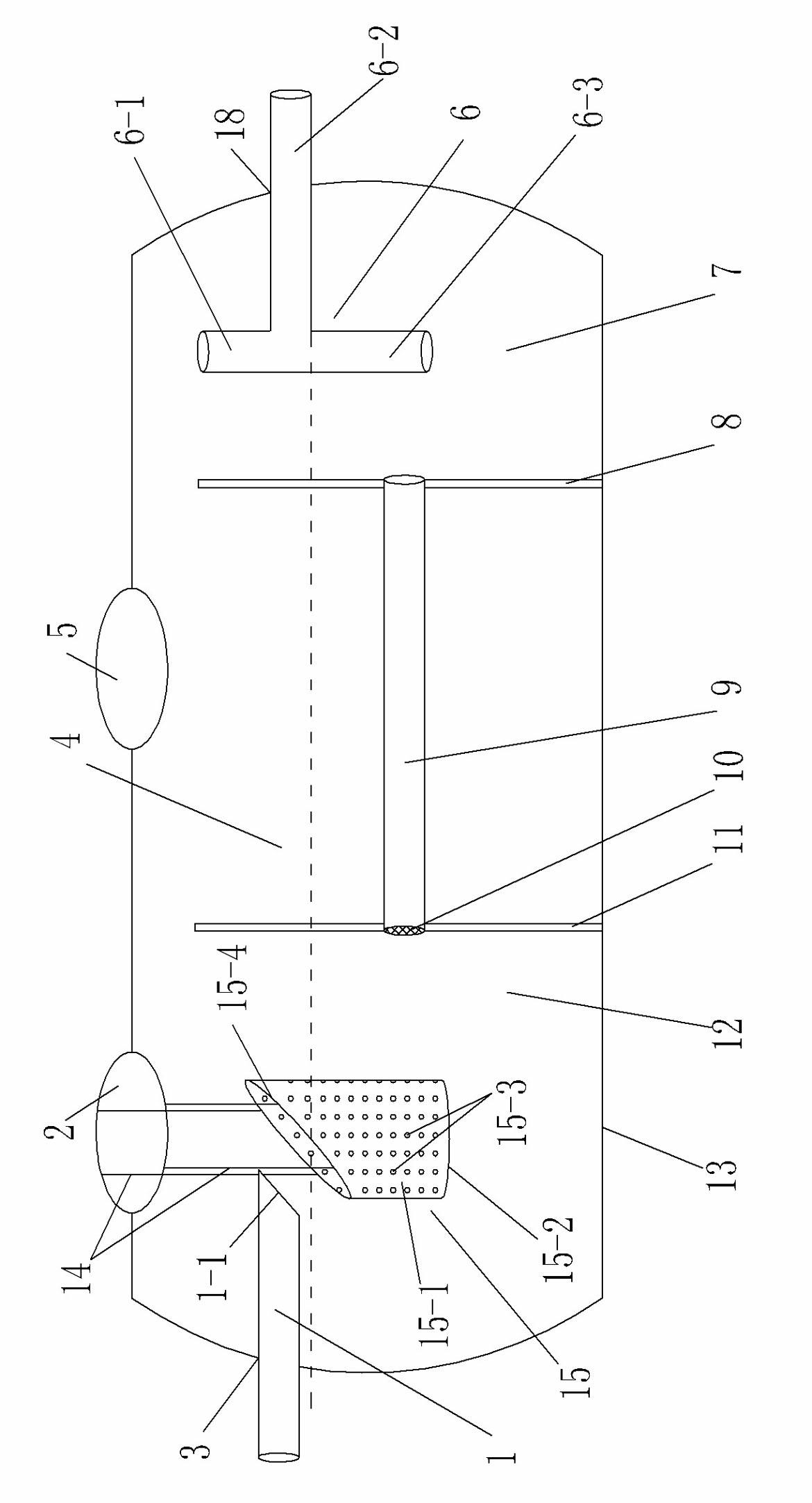
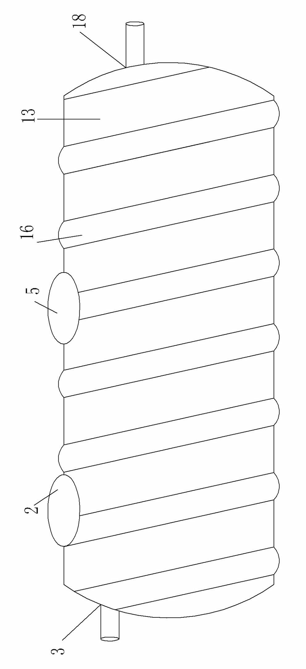
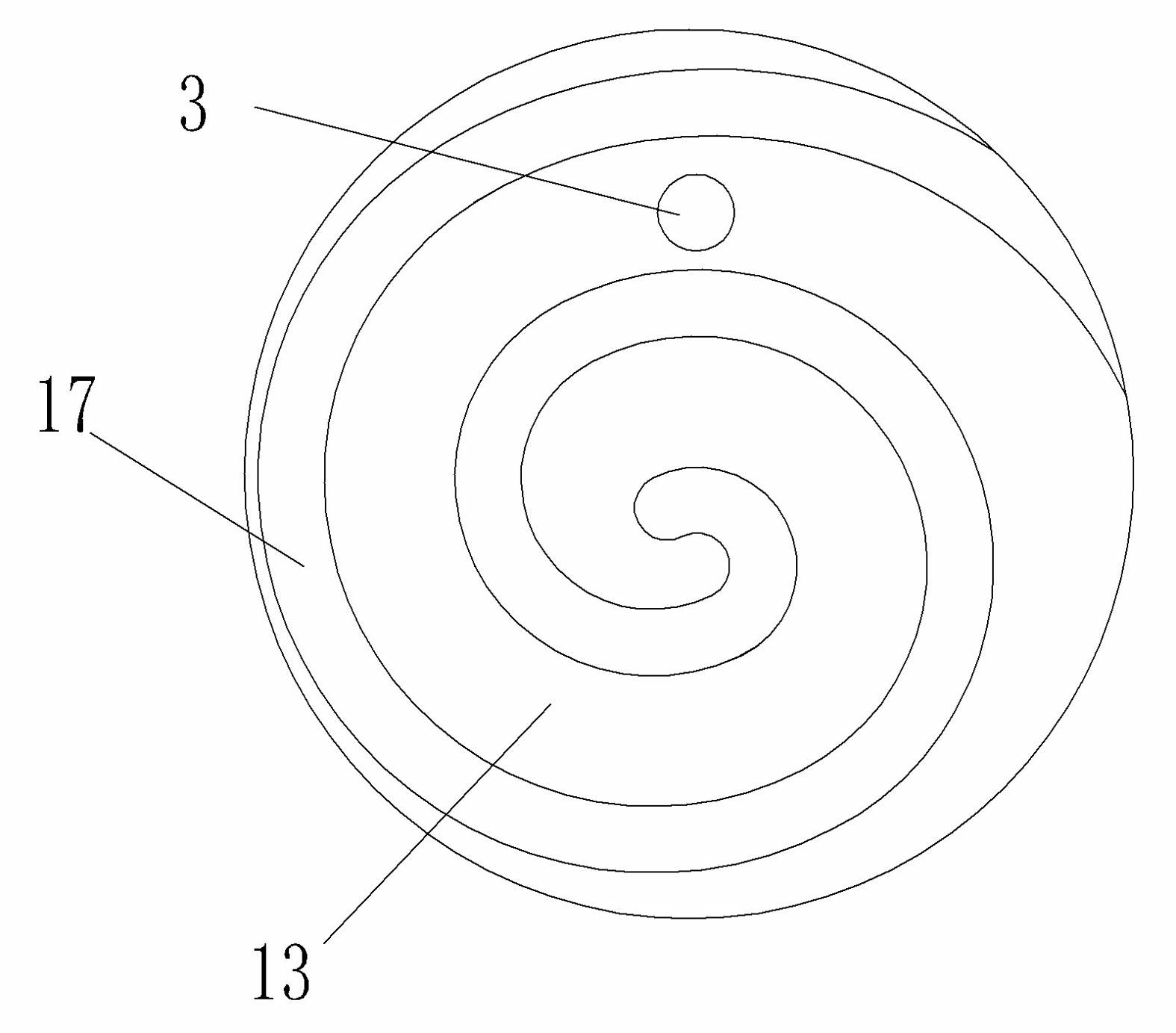
[0022] An embodiment of a slag removal grease trap is for example Figure 1~3 Shown: includes a sealed tank body 13, the tank body 13 is made of integral glass fiber reinforced plastic material, the two ends of the tank body 13 are provided with a vortex-shaped reinforcement structure 17, and the outer periphery of the tank body 13 is provided with a threaded reinforcement structure 16, and the vortex-type reinforcement structure 16 is provided. The tail end of the reinforcing structure 17 is connected with the head end of the threaded reinforcing structure 16 . Inside the tank body 13, a first partition 11 and a second partition 8 are arranged side by side along the corresponding sewage flow direction, and the first partition board 11 and the second partition 8 divide the tank body 13 into a first-stage oil-water separation chamber connected to the upper part. 12. The oil storage bin 4 and the secondary oil-water separation bin 7. The tank body 13 is provided with a slag outl...


PUM


Abstract

The invention relates to a slag removal and oil separation tank. The slag removal and oil separation tank comprises a sealed tank body, wherein a first-stage oil-water separation bin, an oil storage bin and a second-stage oil-water separation bin which are partitioned by a corresponding first partition plate and a corresponding second partition plate and of which the upper parts are communicated are arranged in the tank body; a slag discharge port opposite to the position of the first-stage oil-water separation bin is formed in the tank body; the upper part of the tank body is provided with an oil discharge outlet; a water inlet is formed in the tank body where the first-stage oil-water separation bin is positioned; a water outlet of which the height is smaller than that of the water inlet is formed in the tank body where the second-stage oil-water separation bin is positioned; a water guidance channel for communicating the first-stage oil-water separation bin and the second-stage oil-water separation bin is formed at a position which is lower than the water outlet between the first partition plate and the second partition plate; a water guidance channel filter screen for preventing corresponding waste residue from flowing in fdcbg.dto the second-stage oil-water separation bin from the first-stage oil-water separation bin is arranged in the water guidance channel; and a water inlet pipe of which one end is communicated with the water inlet and the other end extends into the first-stage oil-water separation bin is arranged at the water inlet. By separating water and greasy dirt layer by layer, the invention provides a slag removal and oil separation tank which has a preferable oil-water separation effect.

Description

technical field [0001] The invention relates to sewage treatment equipment, in particular to an underground multi-stage glass fiber reinforced plastic slag removal and oil separation tank. Background technique [0002] The wastewater discharged from restaurants, guesthouses, schools, corporate offices and other large catering establishments contains a large amount of oil. If it is directly discharged into urban sewage pipes, it will not only cause greater pollution, but also increase the difficulty of sewage treatment. At the same time, the oily water contains a lot of organic components, which are directly discharged into the sewage pipes, and the oily liquid adheres to the sewer pipes to form a thick greasy layer, which causes pipeline blockages, is difficult to dredge, and produces odors and breeds germs, polluting the surrounding environment. Therefore, before the catering sewage containing a large amount of oil is discharged into the urban sewage pipe, the oil can be ex...

Claims


Application Information

Patent Timeline
Patent Type & Authority Applications(China)
IPC IPC(8): B01D36/04C02F1/40
Inventor 许卫靖许海岳
Owner 许卫靖
Why Eureka
Try Eureka