Sliding water gap device capable of preventing vortex

A sliding nozzle and vortex technology, which is applied in casting melt containers, metal processing equipment, casting equipment, etc., can solve the problems of increasing the purchase cost and manufacturing cost of refractory materials, increasing the content of steel inclusions, and reducing the purity of the casting billet, etc. Achieve the effect of improving the quality of the slab, reducing the production cost and reducing the consumption of refractory materials

Inactive Publication Date: 2012-07-11
WISDRI ENG & RES INC LTD
View PDF11 Cites 10 Cited by
  • Summary
  • Abstract
  • Description
  • Claims
  • Application Information

AI Technical Summary

Problems solved by technology

However, these suppression methods, including the floating valve method, cannot completely block the vertical inflow of molten steel directly above the nozzle, so the effect of suppressing the converging vortex is not very satisfactory, and these methods need to add additional Devices will inevitably increase the purchase cost and manufacturing cost of refractory materials. At the same time, the devices made of these refractory materials will fall off into the molten steel after being continuously scoured in the molten steel, thereby increasing the inclusion content in the steel and reducing the casting slab. Purity, deterioration of billet quality

Method used


Image

  • Sliding water gap device capable of preventing vortex
  • Sliding water gap device capable of preventing vortex
  • Sliding water gap device capable of preventing vortex

Examples


Embodiment Construction

[0024] In order to facilitate a further understanding of the structure and achieved effects of the present invention, preferred embodiments are described in detail below in conjunction with the accompanying drawings.

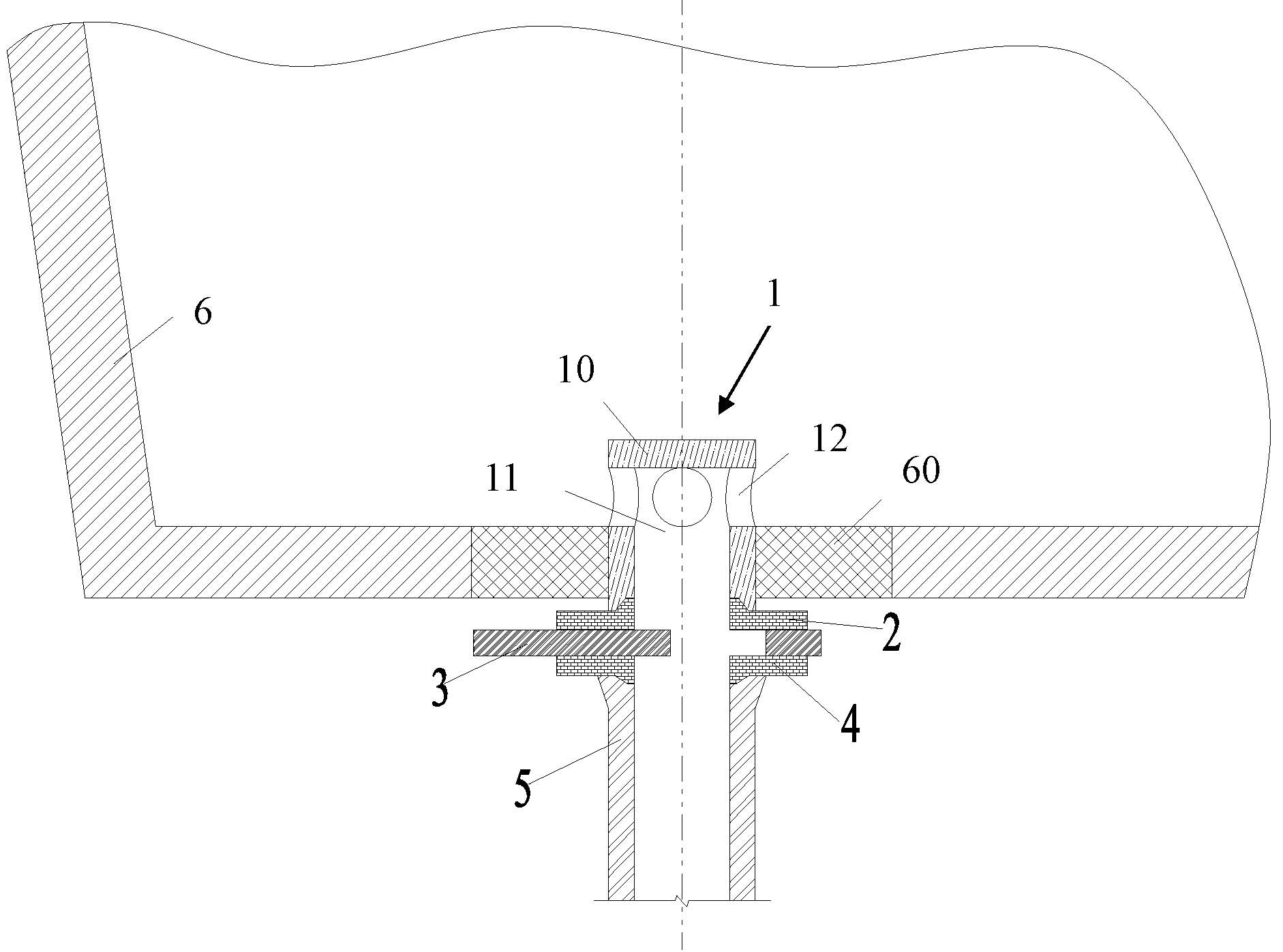
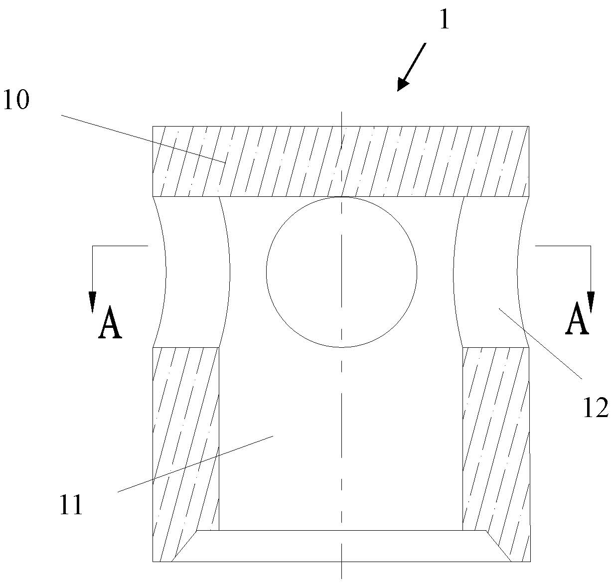
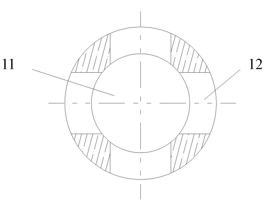
[0025] Such as Figure 1 to Figure 3 As shown, the sliding nozzle device of the present invention includes from top to bottom an upper nozzle 1, an upper sliding plate 2 fixedly connected to the bottom of the upper nozzle, a middle sliding plate 3 connected to the upper sliding plate 2, a lower sliding plate 4 connected to the middle sliding plate 3 and The lower nozzle 5 fixedly connected with the lower plate 4 and the upper nozzle 1 are fixed together with the seat brick 60 on the bottom surface of the pouring container 6 , and the bottom end of the upper nozzle 1 is located at the lower surface of the seat brick 60 . The best shape of the upper nozzle 1 is a cylinder, and in special cases, it can also be a cube with chamfers. The top surface of the upper noz...


PUM


Abstract

The invention discloses a sliding water gap device capable of preventing vortex. The sliding water gap device comprises an upper water gap, an upper sliding plate fixedly connected to the bottom of the upper water gap, a middle sliding plate which is connected with the upper sliding plate and capable of doing reciprocating motion in a horizontal direction, a lower sliding plate connected with the middle sliding plate and a lower water gap fixedly connected with the lower sliding plate, wherein a sealed cover plate is arranged on the top of the upper water gap; an opening is formed at the bottom of the upper water gap; a vertical middle hole is formed in the upper water gap; a plurality of circular side holes with the same shape and size are uniformly formed in the side face of the upper water gap and communicated with the middle hole; longitudinally perforative inner holes are formed in the middles of the upper sliding plate, the middle sliding plate, the lower sliding plate and the lower water gap; and the inner holes and the middle hole form steel liquid flow channels. According to the sliding water gap device, the residual steel quantity in a casting container can be reduced, the metal yield can be increased, and involved slag and air can be reduced.

Description

technical field [0001] The invention relates to a sliding nozzle structure in continuous casting technology, in particular to a sliding nozzle device installed on a continuous casting tundish or ladle to prevent vortex generation. Background technique [0002] With the rapid development of steelmaking technology and high-efficiency continuous casting, the sliding nozzle system has become more and more important in the modern iron and steel smelting process, and has become an indispensable part of smelting. It is a control device for molten steel in the casting process of the continuous casting machine. It can accurately adjust the flow of molten steel from the ladle to the continuous casting tundish. A balance is achieved which makes the continuous casting operation easier to control. The sliding nozzle system has been developed rapidly because of its good controllability, convenient loading and unloading, safety and reliability, and the ability to improve steelmaking prod...

Claims


Application Information

Patent Timeline
Patent Type & Authority Applications(China)
IPC IPC(8): B22D41/24
Inventor 徐海伦马春武幸伟徐永斌邵远敬叶理德
Owner WISDRI ENG & RES INC LTD
Why Eureka
Try Eureka