Supercharge Your Innovation With Domain-Expert AI Agents!

Automatic scar removing machine for timbers

A wood and automatic technology, applied in fixed drilling machines and other directions, can solve the problems of low processing efficiency, high labor intensity, different shrinkage and expansion, etc., and achieve the effect of improving work efficiency, simplifying processing technology, and being convenient to move.

Active Publication Date: 2012-07-11
漳州喜梦宝家居科技有限公司
View PDF7 Cites 6 Cited by
  • Summary
  • Abstract
  • Description
  • Claims
  • Application Information

AI Technical Summary

Problems solved by technology

[0002] At present, in the process of processing wood into furniture, if the scars in the wood are not removed, the surface of the product is not easy to process flat, thus affecting the appearance of the furniture product
At the same time, because the scarring composition in wood is different from the composition of other parts of wood, during the processing of wood, scarring in wood is affected differently from other parts by temperature and pressure, which leads to different shrinkage and expansion of each part of processed wood. , thereby affecting the quality and appearance of the product
At present, wood is generally scraped manually before processing. This operation method is not only low in processing efficiency and labor-intensive, but also the surface of the scar-removing hole in the wood block is uneven, which increases the difficulty of filling the scar-removing hole. The scar hole can only be artificially filled with wood chips

Method used


Image

  • Automatic scar removing machine for timbers
  • Automatic scar removing machine for timbers
  • Automatic scar removing machine for timbers

Examples


Embodiment Construction

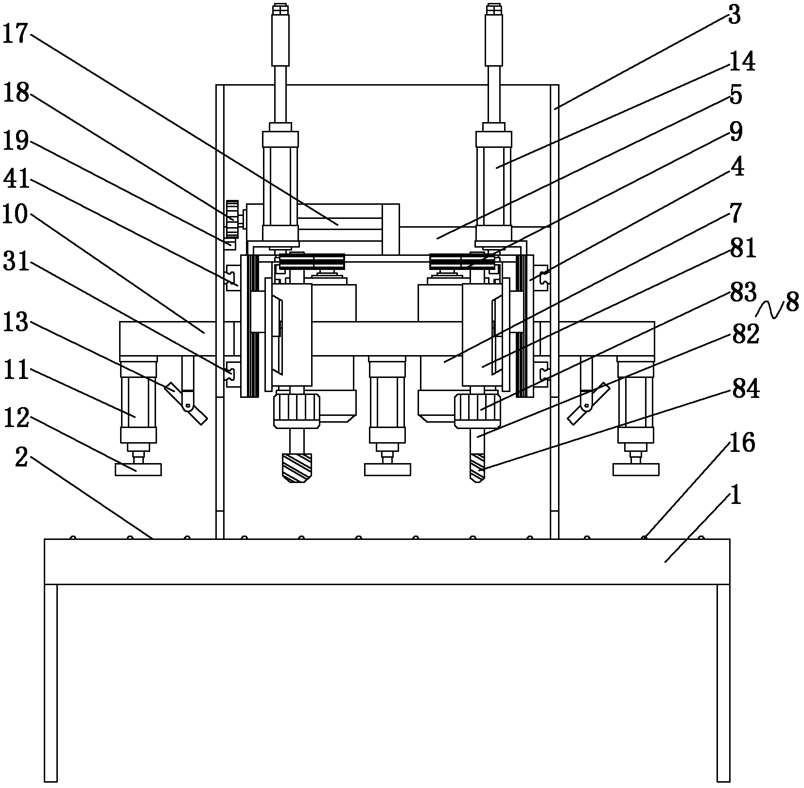
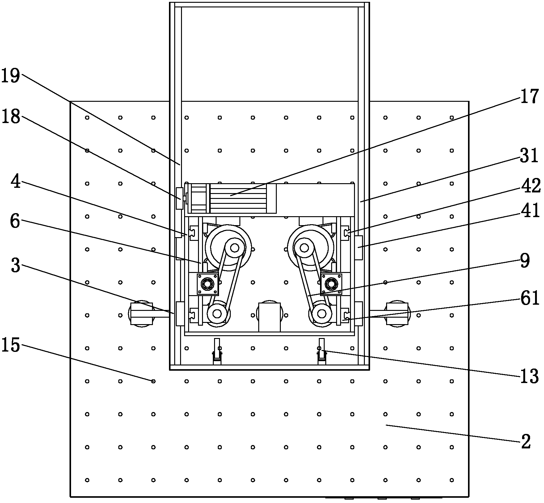
[0015] Such as figure 1 or figure 2 As shown, the wood automatic scar removal machine of the present invention comprises a frame 1, an air flotation workbench 2 is arranged on the frame 1, and two support plates 3 are arranged on the air flotation workbench 2 upper sides of the frame 1, and the two support plates The front and rear moving plates 4 that move forward and backward along the support plate 3 are respectively arranged on the plate 3, and cross beams 5 are arranged between the front and rear moving plates 4 on both sides, and the up and down moving plates that move up and down along the front and rear moving plates 4 are respectively provided on the two front and rear moving plates 4 6. Turning milling motor 7 and drill bit device 8 are fixed on each side up and down moving plate 6. Turning milling motor 7 drives the drill bit 84 in the drill bit device 8 to rotate through the transmission belt 9. The drill bit 84 is located above the air flotation workbench 2. The...


PUM


Abstract

The invention discloses an automatic scar removing machine for timbers. The automatic scar removing machine comprises a stand, wherein an air floatation workbench is arranged on the stand, two supporting plates are arranged above the stand, a front moving plate and a back moving plate are respectively arranged on the two supporting plates and are respectively provided with an upper moving plate and a lower moving plate, a rotary milling motor and a drilling device are fixed on the upper moving plate and the lower moving plate at each side, the rotary milling motor drives a drill bit of the drilling device to rotate through a belt, the front moving plate and the back moving plate are further fixedly provided with transverse rods, two lateral supporting rods pass through the two ends of the transverse rods, and a pressing plate is respectively arranged on two sides of the drill bit and is used for locating timbers to be machined; and the transverse rods are further fixedly provided with infrared spotlights for crossly locating scar positions of the timbers. According to the automatic scar removing machine for the timbers, disclosed by the invention, the timbers to be machined conveniently move on the air floatation workbench and are firmly located when subjected to a scar removing operation; in addition, the drill bit rotates at high speed so that the surface of a scar-removed hole after finishing machining is smooth, and a timber repairing block can be directly filled into the scar-removed hole; therefore, the efficiency of the scar removing operation is improved, and a post-stage machining process of filling the scar-removed hole is simplified.

Description

technical field [0001] The invention relates to a wood processing equipment, in particular to an automatic wood scar removal machine. Background technique [0002] At present, in the process of processing wood into furniture, if the scars in the wood are not removed, the surface of the product is not easy to be processed flat, thereby affecting the appearance of the furniture product. At the same time, because the scarring composition in wood is different from the composition of other parts of wood, during the processing of wood, scarring in wood is affected differently from other parts by temperature and pressure, which leads to different shrinkage and expansion of each part of processed wood. , thereby affecting the quality and appearance of the product. At present, wood is generally scraped manually before processing. This operation method is not only low in processing efficiency and labor-intensive, but also the surface of the scar-removing hole in the wood block is une...

Claims


Application Information

Patent Timeline
IPC IPC(8): B27C3/04
Inventor 王庆华邱季端
Owner 漳州喜梦宝家居科技有限公司
Features
  • R&D
  • Intellectual Property
  • Life Sciences
  • Materials
  • Tech Scout
  • Unparalleled Data Quality
  • Higher Quality Content
  • 60% Fewer Hallucinations
Learn More