Rolling device of electrode material

A technology of electrode materials and rolling equipment, applied in electrode manufacturing, battery electrodes, lamination, etc., can solve problems such as not raised

Inactive Publication Date: 2012-07-11
HITACHI ENG & SERVICES CO LTD
View PDF6 Cites 12 Cited by
  • Summary
  • Abstract
  • Description
  • Claims
  • Application Information

AI Technical Summary

Problems solved by technology

However, the technology related to the unique anti-wrinkle measures accompanying the thinning of the electrode material foil as described above is a problem arising from the thinning of the base material foil of the electrode material and high-speed pressing in recent years. , so the status quo is that no effective solution to the problem has been proposed so far

Method used


Image

  • Rolling device of electrode material
  • Rolling device of electrode material
  • Rolling device of electrode material

Examples


Embodiment 1

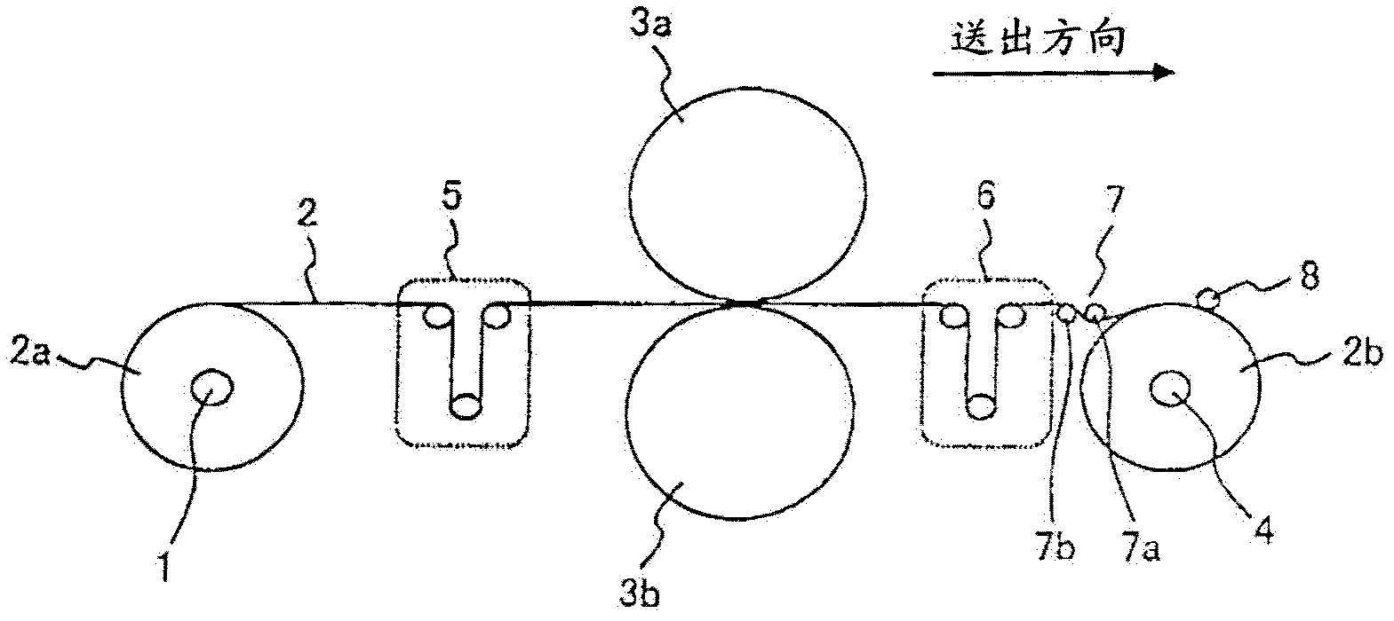
[0027] figure 1 It is a system configuration diagram showing the overall outline of the rolling equipment for electrode materials according to the first embodiment of the present invention. The rolling equipment of this embodiment generally has: an unwinding shaft (uncoiling device) 1 on which an uncoiled roll 2a of the electrode material 2 is wound; rolls (upper pressure roll 3a, lower pressure roll 3b); and a reel (winding device) 4 for winding the compressed electrode material 2 to produce a wound roll 2b. A tension control mechanism 5 for the counter electrode material 2 is provided between the unwinding device 1 (unrolled roll 2a) and the main rolls 3a, 3b. Between the main rolls 3a, 3b and the unwinding device 4 (winding roll 2b), a tension control mechanism 6 and a guide roll mechanism 7 on the winding side (guide rolls 7a, 7b) are provided.

[0028] The guide rollers 7a, 7b are constituted by rollers formed in a convex shape or a true cylindrical shape.

[0029] The...

Embodiment 2

[0052] Figure 4 It is a side view showing the electrode material winding mechanism of the rolling equipment for electrode materials according to the second embodiment of the present invention, Figure 5 express Figure 4 The top view of the electrode material winding mechanism of the embodiment.

[0053] In this embodiment, the main structure of the rolling equipment is the same as that of the first embodiment, and only the differences from the first embodiment will be described here. The same reference numerals as those of the first embodiment denote the same or shared constituent elements.

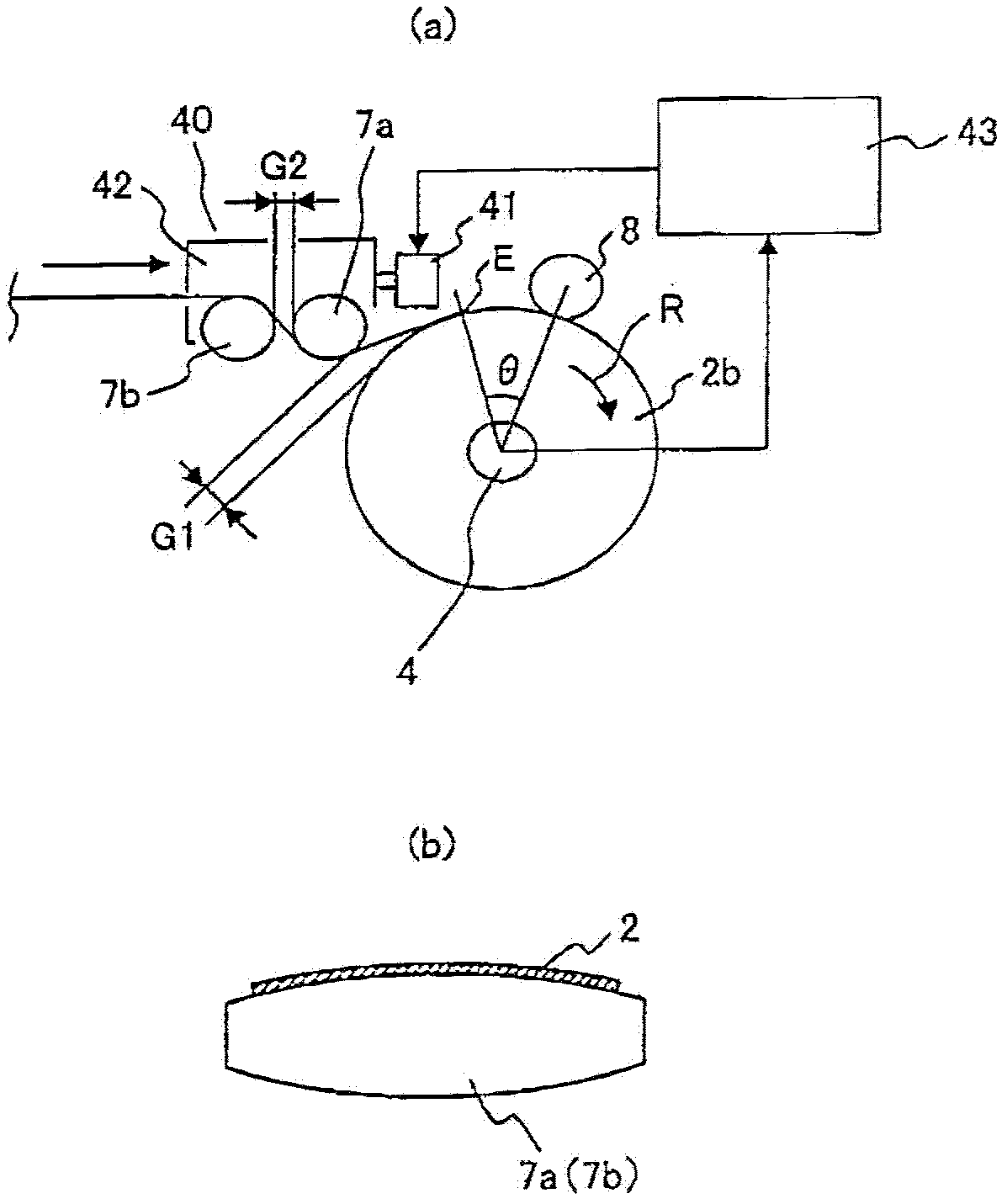
[0054] In the first embodiment, the adjacent guide roller movement control is performed by calculating the outer diameter D of the winding roller 2 b by the control device 43 , but in this embodiment, the control is performed as follows instead. That is, the guide roller movement control mechanism has the winding coil outer diameter detection sensor 71 which performs movement control...

Embodiment 3

[0058] Figure 7 It is a side view showing the electrode material winding mechanism of the rolling equipment for electrode materials according to the third embodiment of the present invention, Figure 8 express Figure 7 The top view of the electrode material winding mechanism of the embodiment.


PUM


Abstract

The invention provides a rolling device of a wrinkle-prevention mechanism of an electrode material corresponding to the thin-film of the base material foil of the strip-shaped electrode material and high speed of the rolling speed of the electrode material. The rolling device can be sued to convey, compact, process and wind the electrode material (2) with active matters coated on the surface of the base body material. The rolling device is provided with a pressurizing roller (7a, 7b) processing the electrode material into the predetermined thickness; a winding device (4) used for winding the compacted electrode material into the winded winds (2b). Guide roller (7a) adjacent to winding device is disposed between an output side of the pressurizing roller and winding device, and disposed on an inner side of the winded winds (2b) to reach the largest outer diameter. The adjacent guide roller 7a can be movably controlled, so that the interval G1 between the adjacent guide roller 7a and the winded winds (2b) can be remained the predetermined value during the winding process.

Description

technical field [0001] The present invention relates to a rolling equipment for conveying and winding an electrode material coated with an active material on both sides of a base material such as aluminum foil or copper foil by a production line, and performing continuous compression processing by a roller. Background technique [0002] For positive and negative electrode materials such as lithium batteries and capacitors, active materials are coated on both sides of strip-shaped base materials such as aluminum foil and copper foil, and then rolled (compression processing) by rolling equipment in the manufacturing process. ) to increase the density of its active material and achieve a uniform thickness. After this roll pressing, the electrode material is wound up on a reel in the form of a roll, and the wound roll is shipped as an electrode material product or transferred to the next process. [0003] In recent years, in order to reduce the battery cost and achieve higher b...

Claims


Application Information

Patent Timeline
Patent Type & Authority Applications(China)
IPC IPC(8): B32B37/10H01M4/04H01G13/00H01G13/02H01M4/139
CPCY02E60/12Y02E60/122Y02E60/10
Inventor 石田郁一多田健一郎
Owner HITACHI ENG & SERVICES CO LTD
Why Eureka
Try Eureka