Supercharge Your Innovation With Domain-Expert AI Agents!

Four-degree-of-freedom connecting rod working mechanism containing composite hinges

A technology of working mechanism and degrees of freedom, applied in the direction of mechanically driven excavators/dredgers, etc., can solve the problems of low carrying capacity, affecting the working efficiency of mechanical equipment, small working space, etc., to achieve high carrying capacity, simplified analysis and size. Design, the effect of large workspace

Inactive Publication Date: 2014-04-16
YANSHAN UNIV
View PDF14 Cites 0 Cited by
  • Summary
  • Abstract
  • Description
  • Claims
  • Application Information

AI Technical Summary

Problems solved by technology

However, most of the existing connecting rod working devices have their own advantages and disadvantages. Some have large working space but low carrying capacity; on the contrary, those with high carrying capacity have small working space, which affects the working efficiency of mechanical equipment.

Method used


Image

  • Four-degree-of-freedom connecting rod working mechanism containing composite hinges
  • Four-degree-of-freedom connecting rod working mechanism containing composite hinges
  • Four-degree-of-freedom connecting rod working mechanism containing composite hinges

Examples


Embodiment 1

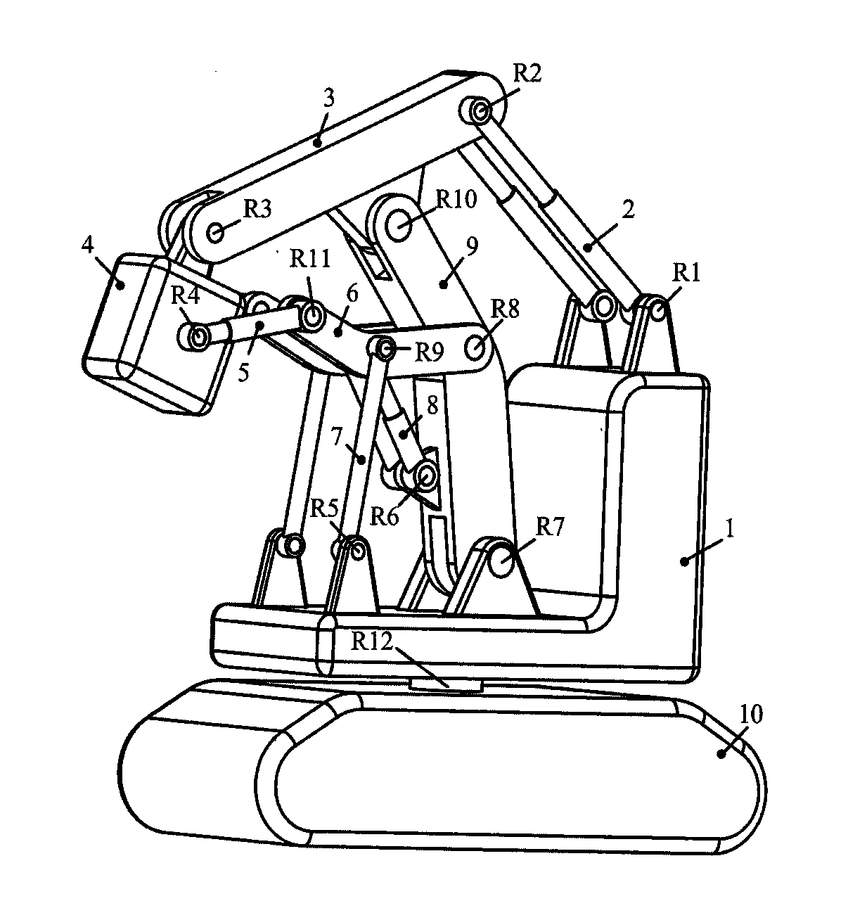
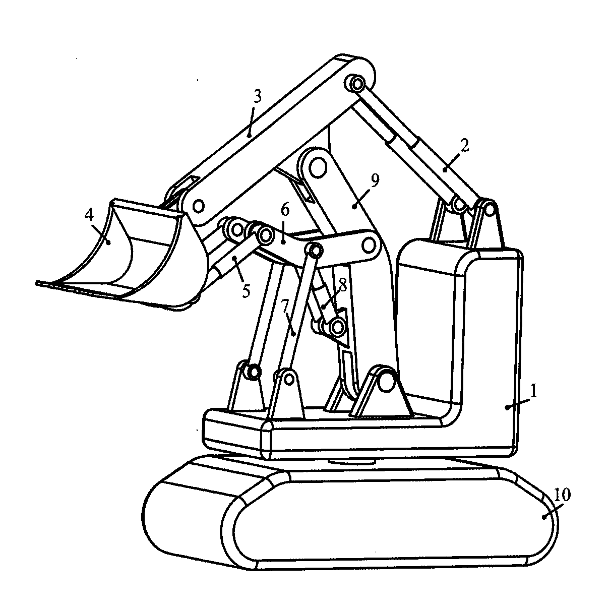
[0017] exist figure 1 In the three-dimensional schematic diagram of Embodiment 1 of a four-degree-of-freedom linkage working mechanism with compound hinges shown, the base 1 is connected to the crawler device 10 through a slewing device, and three pairs of parallel symmetrical bases are arranged on the base, among which The pair of bases in between are connected to the bottom end of the boom 9 through the hinge R7, the top of the boom is connected to the middle part of the forearm 3 through the hinge R10, and one end of the forearm is connected to a part of the end effector 4 through the hinge R3; The other end of the forearm is connected to the piston rod ends of a pair of forearm oil cylinders 2 through a hinge R2, and the cylinder liner end of the forearm oil cylinder is connected to a pair of bases at one end of the base through a hinge R1; The base is connected to one end of a pair of pull rods 7 through a hinge R5, and the pair of pull rods and the piston rod ends of a ...

Embodiment 2

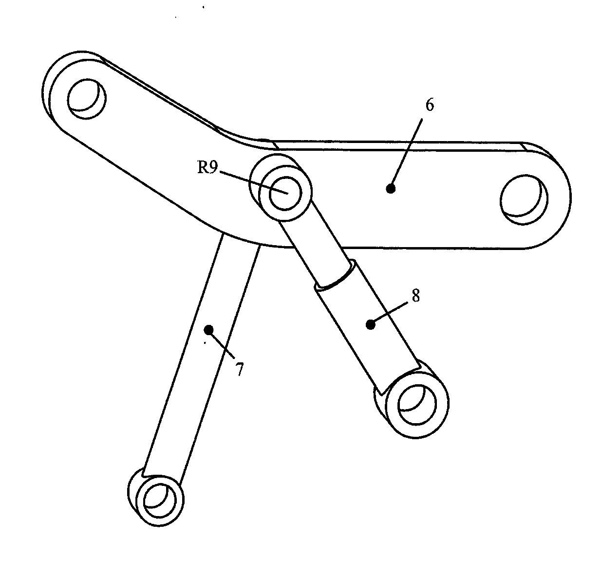
[0021] exist Figure 5 In the three-dimensional schematic diagram of Embodiment 2 of a four-degree-of-freedom connecting rod working mechanism containing compound hinges, the ends of the cylinder liners of a pair of end effector cylinders 5 and one end of a pair of rockers 6 pass through the hinge R9 respectively. Connected to both sides of the middle part of the boom 9 to form two symmetrically distributed compound hinges, the other end of the rocker is connected to the end of the pull rod through the hinge R11, and the connection relationship of other components is the same as figure 1 .


PUM


Abstract

The invention discloses a four-degree-of-freedom connecting rod working mechanism containing composite hinges. A base is connected with a track moving device through a rotating device, three pairs of parallel and symmetrical pedestals are arranged on the base, a pair of pedestals in the middle is hinged with one end of a large arm, the other end of the large arm is hinged with the middle part of a small arm, and one end of the small arm is hinged with an end actuator; the other end of the small arm is hinged with a piston rod of a small arm cylinder, and a cylinder sleeve of the small arm cylinder is hinged with the pedestals at one end of the base; the pedestals at the other end of the base are hinged with one end of a pull rod; the pull rod, a piston rod of a large arm cylinder and the middle part of a rocker are respectively connected through hinges to form two composite hinges distributed symmetrically; a cylinder sleeve of the large arm cylinder is hinged with the large arm, and one end of the rocker is hinged with the middle part of the large arm; and the other end of the rocker is hinged with a cylinder sleeve of an end actuator cylinder, and a piston rod of the end actuator cylinder is hinged with the end actuator. The working mechanism has the advantages of high rigidity, large working space, strong bearing capacity and convenience and instantaneity in control.

Description

technical field [0001] The invention relates to a mechanism innovation of a mechanical arm, especially an innovation of a four-degree-of-freedom link working mechanism including a compound hinge. Background technique [0002] Mechanism is the core of machinery and equipment, and the innovation of mechanism has always been the key to the innovation of machinery and equipment. It is very important to develop corresponding institutions with independent intellectual property rights to improve the core competitiveness of the technological level of my country's machinery and equipment. To realize functional working devices such as excavation, loading, and handling, it is more common to use linkage mechanisms. Chinese patent CN2559619Y relates to a loader forward rotation eight-bar linkage mechanism; Chinese patent CN201687021U relates to a loader forward rotation six-bar linkage mechanism. In addition, common excavator working mechanisms are also composed of linkages. However, mo...

Claims


Application Information

Patent Timeline
Patent Type & Authority Patents(China)
IPC IPC(8): E02F3/38E02F3/42
Inventor 丁华锋曹文熬陈谊超杨凤霞曹宇
Owner YANSHAN UNIV
Features
  • R&D
  • Intellectual Property
  • Life Sciences
  • Materials
  • Tech Scout
  • Unparalleled Data Quality
  • Higher Quality Content
  • 60% Fewer Hallucinations
Learn More