Low flow pulsation hydraulic pressure transformer

A technology of hydraulic transformer and small flow, applied in the field of hydraulic transformer, can solve the problems of poor stability, affecting application, output flow pulsation, etc., achieve the effect of structural optimization, improve working stability, and reduce flow pulsation

Active Publication Date: 2012-07-11
BEIJING INSTITUTE OF TECHNOLOGYGY
View PDF8 Cites 6 Cited by
  • Summary
  • Abstract
  • Description
  • Claims
  • Application Information

AI Technical Summary

Problems solved by technology

For the pump / motor coaxial connection, by adjusting the displacement of the variable motor, the pressure of the oil source can be transmitted at a certain pressure, which can realize the function of the hydraulic transformer. At the same time, the size and weight are very large, and the adjustment mechanism of the variable motor requires a large amount of power, high cost, and low efficiency, which affects its application.
As for the form of the rotary three-port distribution plate, the traditional design adopts the form of a single rotary body. Due to the small number of plungers working on each oil port, there are disadvantages of poor stability in the working process and large output flow pulsation.

Method used


Image

  • Low flow pulsation hydraulic pressure transformer
  • Low flow pulsation hydraulic pressure transformer
  • Low flow pulsation hydraulic pressure transformer

Examples


Embodiment Construction

[0020] The present invention will be described in detail below with reference to the accompanying drawings and examples.

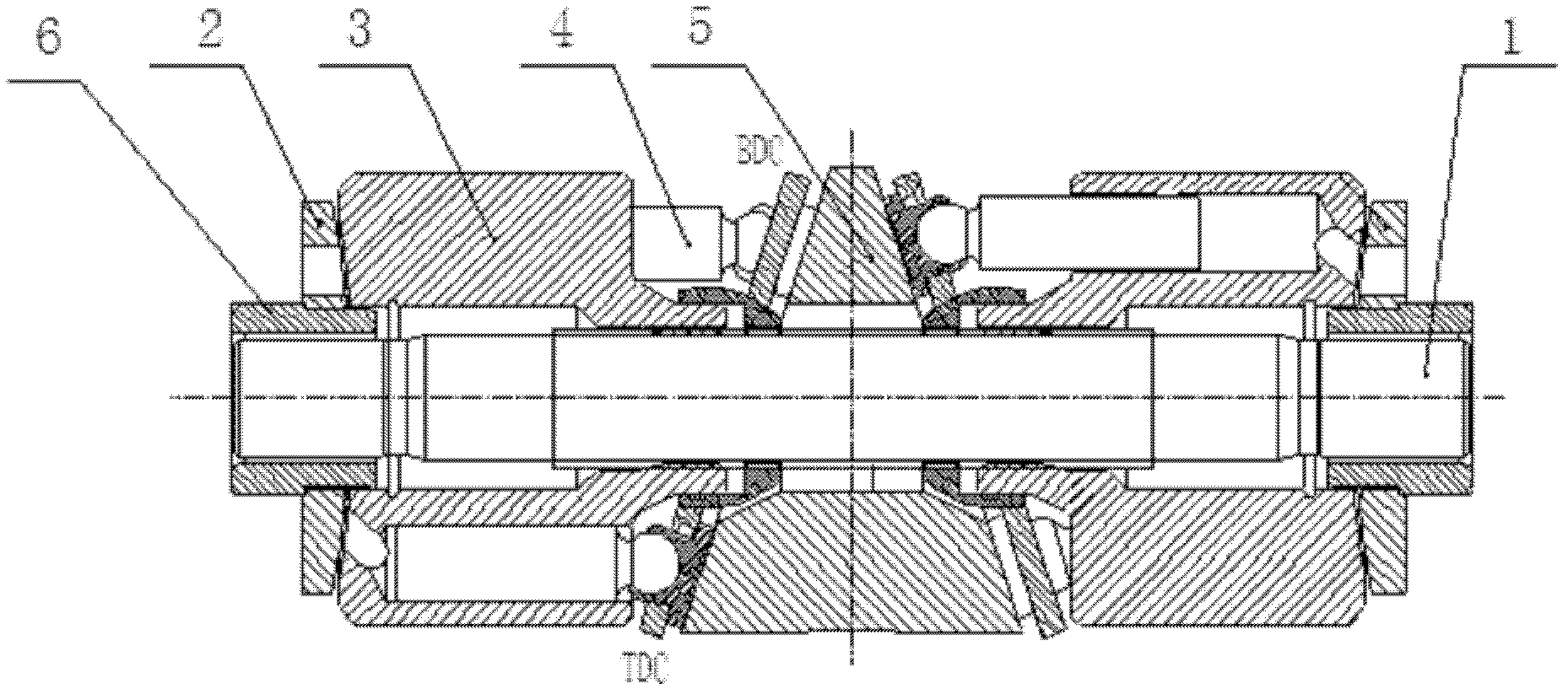
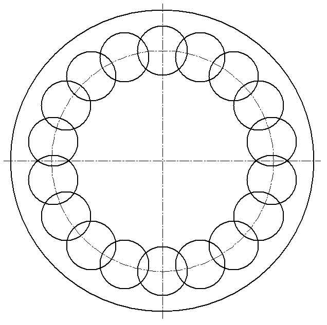
[0021] The small flow pulsation hydraulic transformer provided by the present invention is as figure 1 As shown, the transformer includes a main shaft 1, a swash plate 5, a left transformer component and a right transformer component. The hydraulic transformer adds a right transformer part symmetrical to the left transformer part on the traditional hydraulic transformer, and through the reasonable arrangement of the plunger, the flow pulsation of the hydraulic transformer is reduced, and the working stability of the system is improved.

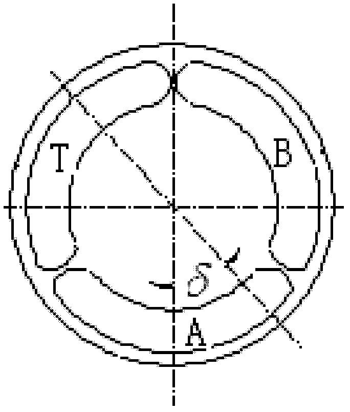
[0022] The swash plate 5 is a conical pedestal, such as Figure 4 As shown, the included angle between the busbar of the conical pedestal and the vertical direction is 15°, the center of the swash plate 5 is horizontally processed with a through hole, the main shaft 1 is installed in the through hole horizontally, and the...


PUM


Abstract

The invention provides a low flow pulsation hydraulic pressure transformer, which comprises a spindle, a tilting tray, a left pressure transformation component and a right pressure transformation component, the tilting tray is a conical column table, a transverse through hole is machined in the center of the tilting tray, the spindle is transversely mounted in the through hole, and the left pressure transformation component and the right pressure transformation component are mounted at the left end and the right end of the spindle respectively and symmetrically arranged along a central axis of the tilting tray. By means of coaxial rotation of double rotators, the number of plungers working at each distributing port is doubled in each moment of the rotation process of the rotators, so that the flow pulsation of the hydraulic pressure transformer can be reduced, and system operation stability is improved. By the aid of the tilting tray capable of bidirectionally and freely rotating around the spindle, the pressure of an oil source can be adjusted to an arbitrary value without energy loss.

Description

technical field [0001] The invention relates to a hydraulic transformer, in particular to a hydraulic transformer with small flow pulsation. Background technique [0002] In the hydraulic control system, due to the large pressure difference in the traditional throttling control method, it will bring a large energy loss. Therefore, in order to transmit the energy of the constant voltage network in a constant power manner like a power transformer, a hydraulic transformer is produced. [0003] Hydraulic transformers are generally in the form of a pump / motor coaxial connection or a rotating three-port valve plate. For the pump / motor coaxial connection form, by adjusting the displacement of the variable motor, the pressure of the oil source is transmitted at a certain pressure, which can realize the function of the hydraulic transformer, but the hydraulic transformer is because the two devices are mechanically connected. At the same time, the volume and weight are very large, a...

Claims


Application Information

Patent Timeline
Patent Type & Authority Applications(China)
IPC IPC(8): F15B3/00
Inventor 吴维苑士华胡纪滨荆崇波吕先法
Owner BEIJING INSTITUTE OF TECHNOLOGYGY
Why Eureka
Try Eureka