Electromagnetic clutch and manufacturing method of coil case thereof

A technology of electromagnetic clutch and manufacturing method, applied in the direction of magnetic drive clutch, clutch, non-mechanical drive clutch, etc., can solve the problems of easy de-soldering, inability to fit well, deformation, etc.

Inactive Publication Date: 2012-07-11
SANDEN HUAYU AUTOMOTIVE AIR CONDITIONING CO LTD
View PDF6 Cites 7 Cited by
  • Summary
  • Abstract
  • Description
  • Claims
  • Application Information

AI Technical Summary

Problems solved by technology

The annular surface area of ​​the connecting plate used in the small compressor is small, so the deformation is particularly obvious during the stamping process
The deformed annular surface cannot fit perfectly with the shell, and it is easy to desolder

Method used


Image

  • Electromagnetic clutch and manufacturing method of coil case thereof
  • Electromagnetic clutch and manufacturing method of coil case thereof
  • Electromagnetic clutch and manufacturing method of coil case thereof

Examples


Embodiment Construction

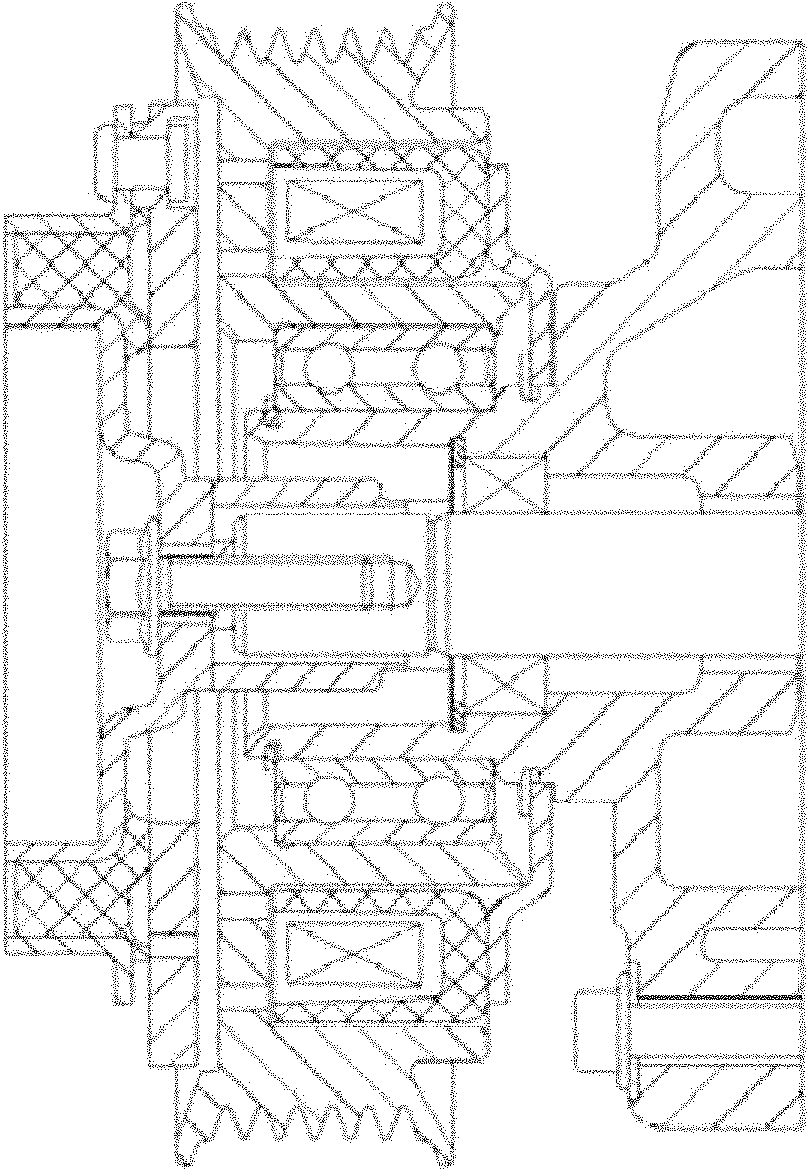
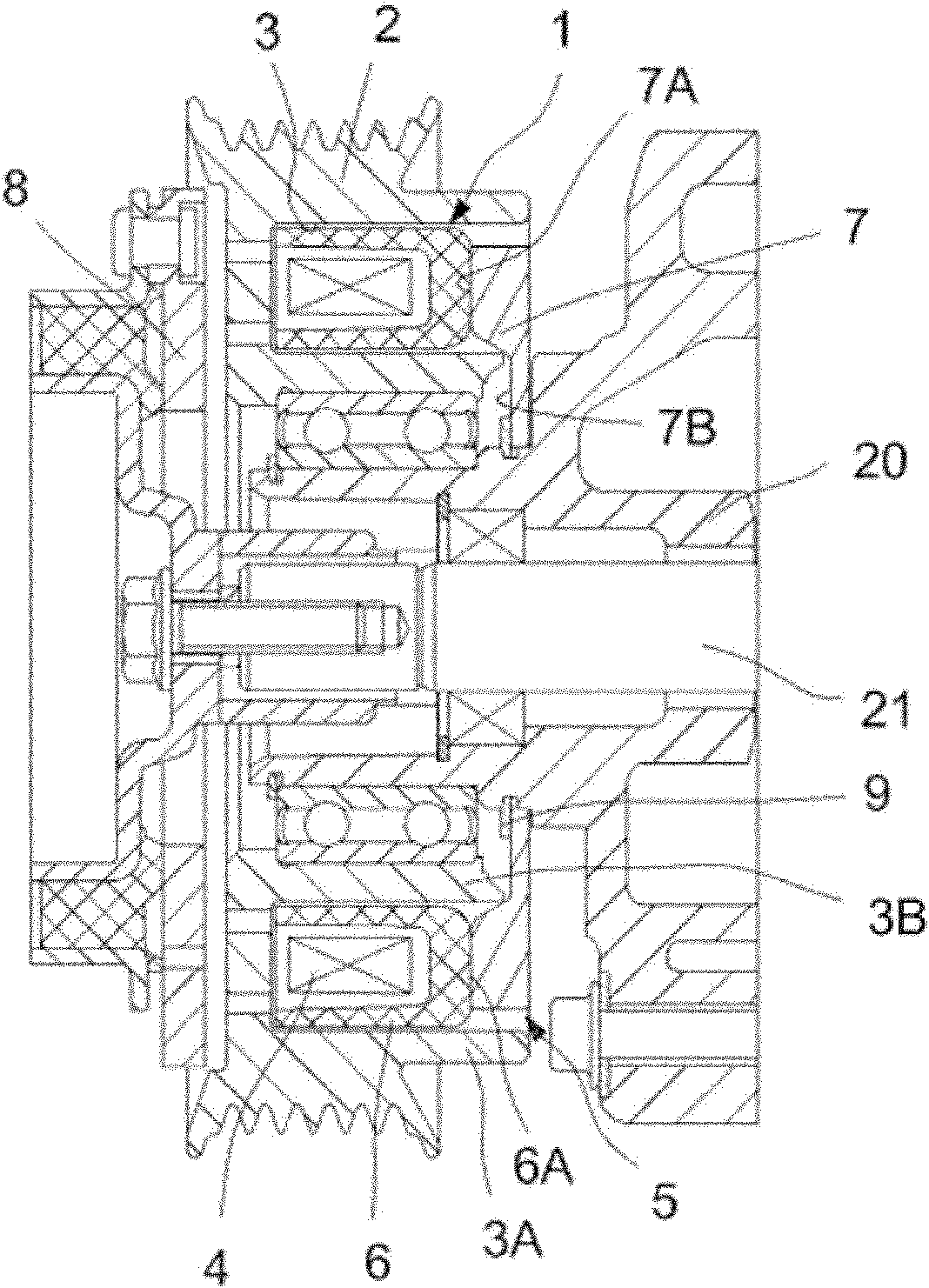
[0026] The electromagnetic clutch is the driving mechanism of the compressor, which is connected to the main shaft of the compressor, and mainly includes a pulley, a coil assembly, and a suction cup. Such as figure 2 As shown, the coil assembly 1 is accommodated in the ring groove 3 of the pulley 2, and the two are not in contact with each other, and there is a gap.

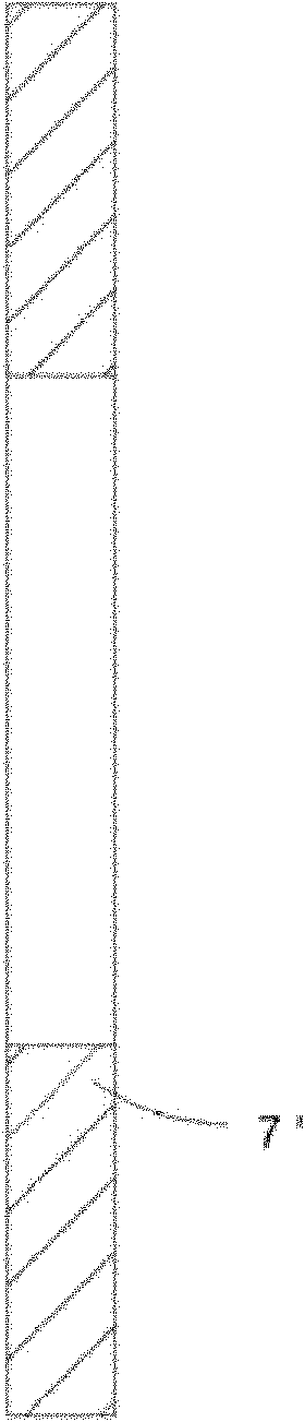
[0027] The coil assembly 1 is mainly composed of a coil 4 and a coil case 5 . The coil housing 5 has a U-shaped tank body 6 , the coil 4 is cast and fixed in the tank body 6 with epoxy resin, and a connecting plate 7 is welded to the back side 6A of the tank body 6 . Such as Figure 4 with Figure 5 As shown, one side of the connecting plate 7 has an outer annular surface 7A and an inner annular surface 7B. The back side 6A of the tank body 6 is welded with the outer ring surface 7A of the connecting plate 7, and the inner ring surface 7B of the connecting plate 7 is fixed on the front cylinder head 20 by, f...


PUM


Abstract

The invention discloses an electromagnetic clutch and a manufacturing method of a coil case thereof. The electromagnetic clutch comprises a coil block which comprises a coil case and a connection plate; the coil case comprises a cell body which is provided with a U-shaped cross section and is used to accommodate a coil; the connection plate is used to assemble the coil block on a front cylinder cover of a compressor; the connection plate is welded on the backside of the cell body; an inside annular face and an outside annular face are formed on one side of the connection plate; the inside annular face is fixed with the front cylinder cover; and the outside annular face is welded with the backside of the cell body. The electromagnetic clutch is characterized in that the inside annular face of the connection plate is a plane processed by cutting process, and on the side of the connection plate, the outside annular face is higher than the inside annular face. The manufacturing method includes the steps of: turning an inner race at one side of a connection plate blank to form the connection plate, so the side of the connection plate is provided with the outside annular face and the inside annular face which is made out through turning process and on the side of the connection plate, the outside annular face is higher than the inside annular face; and welding the outside annular face of the connecting plate with the backside of the cell body of the coil. With the manufacturing method provided by the invention, the weld strength between the coil case and the connection plate is enhanced and the coil case and the connection plate are not easy to loose weld.

Description

technical field [0001] The invention relates to a manufacturing method of an electromagnetic clutch of a compressor and a coil casing thereof. Background technique [0002] Such as figure 1 As shown, the electromagnetic clutch is the driving mechanism of the compressor, which mainly includes a pulley, a coil assembly, a suction cup, and is connected with the suction cup compressor main shaft. The pulley is driven by the car engine. When the coil is energized, the end face generates magnetic force. The pulley and the suction cup generate attraction. The suction cup rotates with the pulley. The suction cup and the main shaft are connected by a key, so that the suction cup can drive the compressor shaft to rotate. [0003] The coil assembly includes a coil and a coil case. The coil housing includes a U-shaped slot body and a connecting plate for assembling the coil assembly on the front cylinder head of the compressor. The coil is accommodated in the U-shaped tank, and the c...

Claims


Application Information

Patent Timeline
Patent Type & Authority Applications(China)
IPC IPC(8): F16D27/14B23P15/00
Inventor 何斌叶伯兴房锦忠
Owner SANDEN HUAYU AUTOMOTIVE AIR CONDITIONING CO LTD
Why Eureka
Try Eureka