Continuously switchable four-way rotary valve

A rotary valve, rotary valve core technology, applied in multi-port valves, valve details, valve devices and other directions, can solve the problems of short service life, frequent valve opening and closing, complex control, etc., to achieve long service life, good sealing, Install simple effects

Active Publication Date: 2012-07-11
HANGZHOU WATER TREATMENT TECH DEV CENT
View PDF4 Cites 15 Cited by
  • Summary
  • Abstract
  • Description
  • Claims
  • Application Information

AI Technical Summary

Problems solved by technology

At present, the reversing valve of the valve-controlled energy recovery device has an annual switching frequency of up to 1 million times, and conventional electromagnetic reversing valves and electric reversing valves cannot be used.
[0004] The energy recovery device described in Chinese patent 03101867.X uses multiple three-way valves to realize the pressure exchange process. This design has three disadvantages: First, it is difficult to ensure the synchronization of valve opening and closing actions, and the system control is complicated ; Second, due to the frequent opening and closing of the valve during the operation of the device, the service life is short, and the third is prone to leakage

Method used


Image

  • Continuously switchable four-way rotary valve
  • Continuously switchable four-way rotary valve
  • Continuously switchable four-way rotary valve

Examples


Embodiment 1

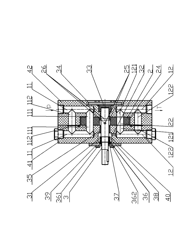
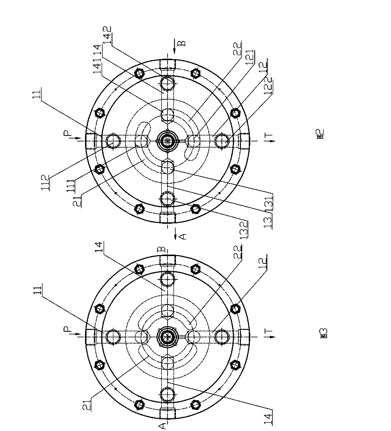
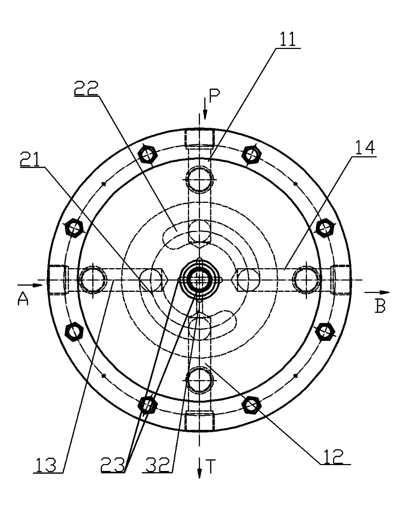
[0041] Embodiment 1, with reference to Figure 1-4 .

[0042] The four-way rotary valve includes a valve body and a rotary valve core 2 .

[0043] The valve body is provided with a first fluid passage 11, a second fluid passage 12, a third fluid passage 13, and a fourth fluid passage 14 in the axial direction and front and back of the rotary valve core, and the communication between the first fluid passage 11 and the outside world The port P is dedicated to water intake, the communication port T between the second fluid channel 12 and the outside world is dedicated to water outlet, the communication port A between the third fluid channel 13 and the outside world is used for water outlet and water intake, and the communication port between the fourth fluid channel 14 and the outside world B is used for water outlet and water intake, and the order along the circumference of the rotary valve core 2 is the first fluid channel 11, the third fluid channel 12, the second fluid chann...

Embodiment 2

[0056] Embodiment 2, with reference to attached Figure 5-8 .

[0057] The four-way rotary valve includes a valve body and a rotary valve core 2, and the rotary valve core 2 is connected to a stepped shaft 3 to be driven by a motor.

[0058] Along the axial direction of the stepped shaft, the four-way rotary valve is provided with a plurality of valve body units, and the valve body units are divided into end units and the same intermediate unit, with the end where the stepped shaft passes through the valve body as the top , the end unit is an upper unit 41 and a bottom unit 42. In this embodiment, there are 3 intermediate units whose labels are respectively 43, 44, and 45. The valve body is connected by bolts by the valve body unit. As a result, a valve core 2 is provided between the valve bodies of adjacent units, and the two adjacent valve body units are sealed with seals outside the valve core 2. With this structure, each intermediate unit can be made the same to improve ...


PUM


Abstract

The invention relates to a continuously switchable four-way rotary valve, which comprises a rotating component and a non-rotating component. The rotating component mainly comprises a driving shaft, a rotary valve spool, a mandrel connecting pin and a shaft sleeve, wherein the rotary valve spool is provided with two arc through hole type fluid channels, and the rotary valve spool is connected with the driving shaft by the aid of the mandrel connecting pin. The continuously switchable four-way rotary valve can be superposed, and rotary valve units can be increased as needed. The continuously switchable four-way rotary valve is driven by a motor, can be continuously switched, and is free of impact during switching, long in service life and particularly suitable for serving as a high-concentration seawater guide valve for a reverse osmosis seawater desalinization energy recovery device.

Description

technical field [0001] The invention relates to a continuously switchable four-way rotary valve, in particular to a four-way rotary valve used in a reverse osmosis seawater desalination energy recovery device. Background technique [0002] Reverse osmosis membrane seawater desalination has been widely used in countries all over the world. my country has made great progress in recent years and will become the mainstream technology of seawater desalination industry in my country in the future. The energy recovery device is one of the key equipment of the reverse osmosis seawater desalination system, which is very important to greatly reduce the energy consumption of the system operation and the cost of water production. Therefore, the research and development of energy recovery technology and devices with my country's independent intellectual property rights is of great significance to breaking the monopoly position of foreign products in the domestic market, further reducing ...

Claims


Application Information

Patent Timeline
Patent Type & Authority Applications(China)
IPC IPC(8): F16K11/08F16K11/10F16K27/06F16K41/00C02F1/44C02F103/08
CPCY02A20/131
Inventor 张希建张建中赵浩华周倪民
Owner HANGZHOU WATER TREATMENT TECH DEV CENT
Why Eureka
Try Eureka