Solar-heating assisted salt melting system

A technology of auxiliary heating and molten salt system, applied in the field of molten salt equipment, can solve the problems of large fuel consumption and large environmental impact, and achieve the effects of increasing heat exchange time, convenient exhaust and improving thermal efficiency

Active Publication Date: 2012-07-11
HANGZHOU BOILER GRP CO LTD
View PDF9 Cites 21 Cited by
  • Summary
  • Abstract
  • Description
  • Claims
  • Application Information

AI Technical Summary

Problems solved by technology

[0003] The purpose of the present invention is to overcome the shortcomings of the current molten salt system, which consumes a lot of fuel and has a great impact on the environment, and provides a solar-assisted heating molten salt system with less fuel consumption and less impact on the environment

Method used


Image

  • Solar-heating assisted salt melting system
  • Solar-heating assisted salt melting system
  • Solar-heating assisted salt melting system

Examples


Embodiment 1

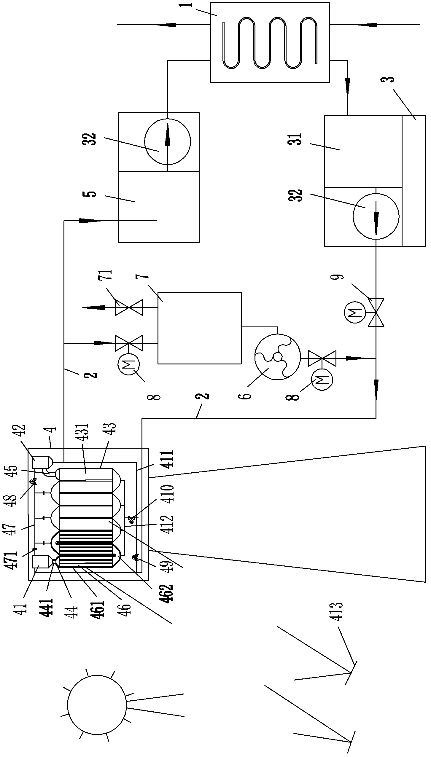
[0022] Embodiment 1, as attached figure 1 , attached figure 2 Shown: a solar-assisted heating molten salt system, including a molten salt furnace 3, a heat-using device 1, a solar heat-absorbing device 4, two heating pipes 2 and a high-temperature salt storage tank 5 with a molten-salt pump 32; The solar assisted heating molten salt system has a preheating device for preheating the heating pipe 2.

[0023] Described molten salt furnace 3 has the low-temperature salt storage tank 31 that has molten salt pump 32, and heat device 1 is a steam generator; The inlet of the heat absorbing device 4 is communicated, the outlet of the solar heat absorbing device 4 is communicated with the inlet of the high-temperature salt storage tank 5 through another heating pipe 2, and the outlet and the import of the heat-using device 1 are connected with the inlet and the inlet of the low-temperature salt storage tank 31 respectively. The outlet of the molten salt pump 32 of the high temperatur...

Embodiment 2

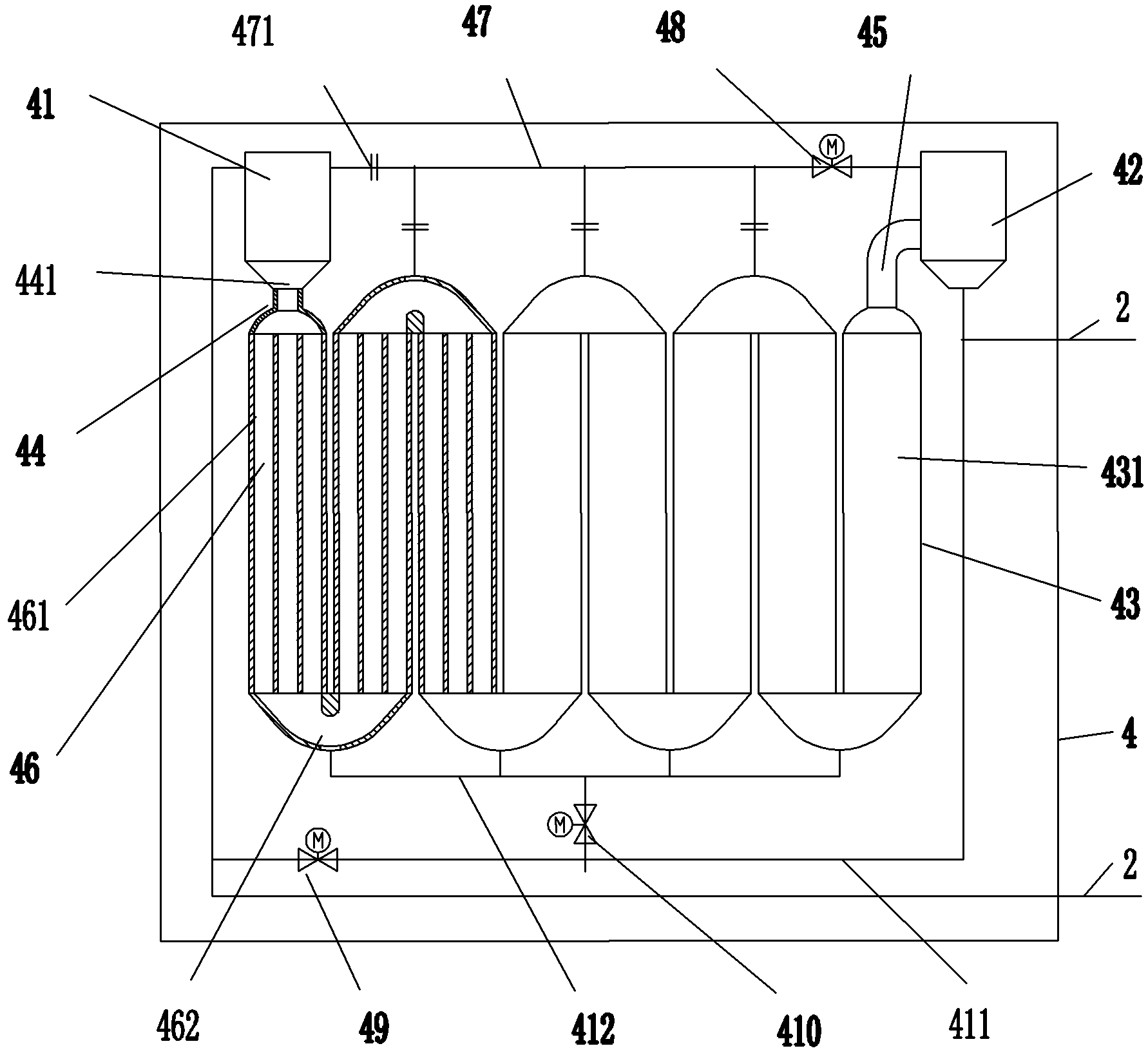
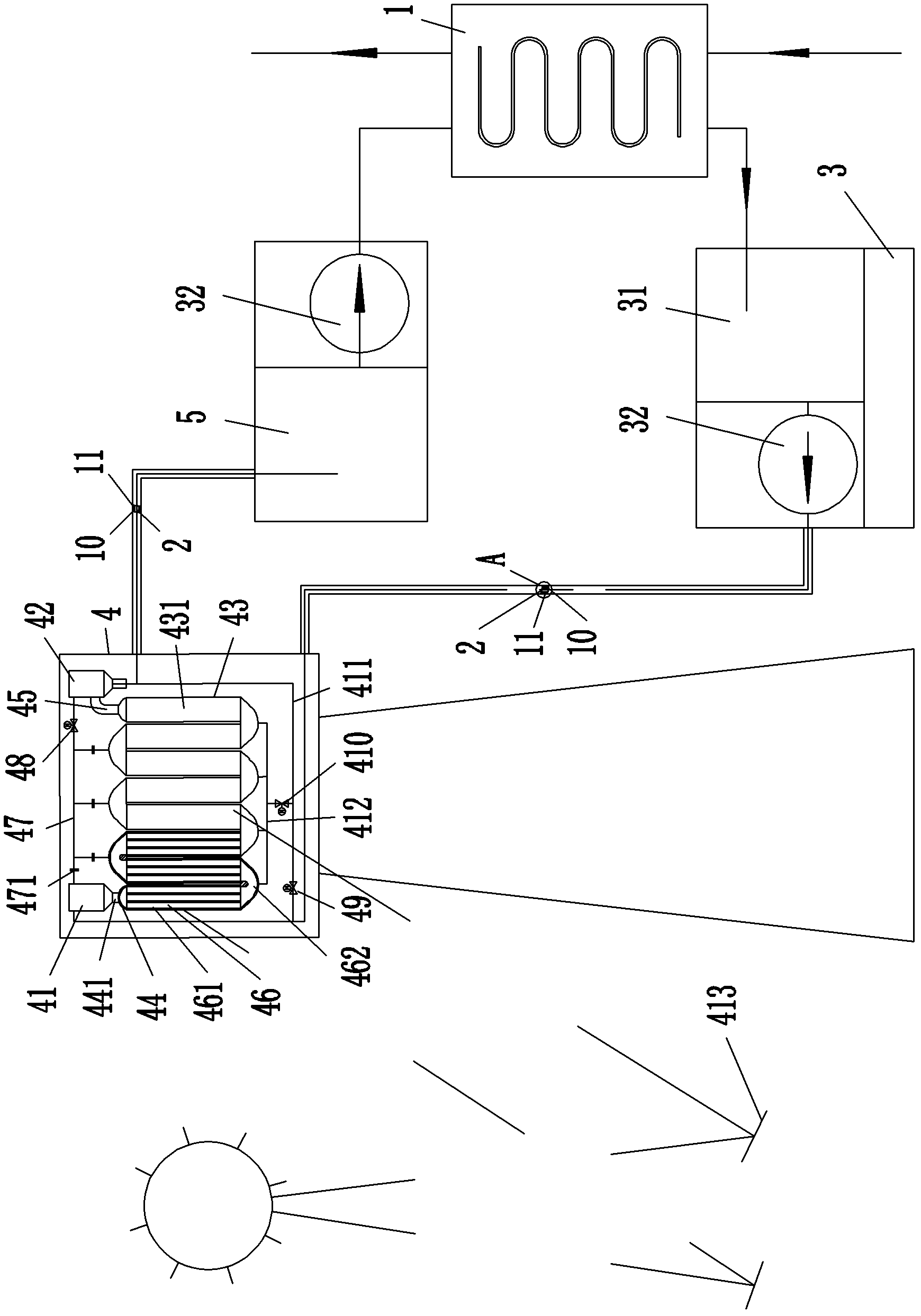
[0029] Embodiment 2, as attached figure 2 , attached image 3 , attached Figure 4 Shown: a solar-assisted heating molten salt system, including a molten salt furnace 3, a heat-using device 1, a solar heat-absorbing device 4, two heating pipes 2 and a high-temperature salt storage tank 5 with a molten-salt pump 32; The solar assisted heating molten salt system has a preheating device for preheating the heating pipe 2.

[0030] Described molten salt furnace 3 has the low-temperature salt storage tank 31 that has molten salt pump 32, and heat device 1 is a steam generator; The inlet of the heat absorbing device 4 is communicated, the outlet of the solar heat absorbing device 4 is communicated with the inlet of the high-temperature salt storage tank 5 through another heating pipe 2, and the outlet and the import of the heat-using device 1 are connected with the inlet and the inlet of the low-temperature salt storage tank 31 respectively. The outlet of the molten salt pump 32 ...


PUM


Abstract

The invention belongs to the field of the salt melting equipment and aims to provide a solar-heating assisted salt melting system which consumes less fuel and less affects the environment. The solar-heating assisted salt melting system comprises a salt melting furnace and a heating device, wherein the salt melting furnace is provided with a low-temperature salt storage tank with a salt melting pump; the solar-heating assisted salt melting system further comprises a solar heat absorbing device, two heating pipes and a high-temperature salt storage tank with a salt melting pump; the outlet of the salt melting pump of the low-temperature salt storage tank is communicated with the inlet of the solar heat absorbing device through a first heating pipe; the outlet of the solar heat absorbing device is communicated with the high-temperature salt storage tank through a second heating pipe; the outlet and the inlet of the heating device are communicated with the inlet of the low-temperature salt storage tank and the outlet of the salt melting pump of the high-temperature salt storage tank respectively; and the solar-heating assisted salt melting system is provided with a preheating device used for preheating the heating pipes. The solar-heating assisted salt melting system consumes less fuel and less affects the environment.

Description

technical field [0001] The invention relates to the field of molten salt equipment, in particular to a solar-assisted heating molten salt system with less fuel consumption and less impact on the environment. Background technique [0002] Molten salt has a high heat capacity and a wide range of liquid-phase operating temperatures. It is a heat-carrying medium with good performance and can provide high temperature; Thermal device composition; the invention of Chinese patent announcement number CN101625155A discloses a generator coal gas molten salt furnace, which uses CO and H2 mixed gas produced by a water gas generator as fuel, and burns and heats the molten salt on the inner wall of the molten salt furnace in the furnace of the molten salt furnace. The salt heating coil, after the heated molten salt flows out of the molten salt furnace, it undergoes sufficient heat exchange with the heating device, and after releasing heat, it can flow back to the molten salt furnace for ci...

Claims


Application Information

Patent Timeline
Patent Type & Authority Applications(China)
IPC IPC(8): F24H7/00F24J2/00F24J2/46F22B1/06
CPCY02E10/40
Inventor 赵剑云姚飞奇刘可亮
Owner HANGZHOU BOILER GRP CO LTD
Why Eureka
Try Eureka