
Simultaneous fluorescence correlation spectroscopy

A fluorescence correlation and spectroscopy technology, applied in the field of simultaneous fluorescence correlation spectroscopy, can solve the problems of not being considered widely used, manufacturing cost, etc.

Inactive Publication Date: 2012-07-11
鲁道夫.格罗斯科夫
View PDF6 Cites 0 Cited by
  • Summary
  • Abstract
  • Description
  • Claims
  • Application Information

AI Technical Summary

Problems solved by technology

But unfortunately it has to be admitted that these instruments are expensive to manufacture and are therefore hardly considered for widespread use for economic reasons
And can only be measured at one location of the sample at the same time, although the chemical and / or biochemical events worth studying in the sample occur at a very large number of locations at the same time

Method used


Image

  • Simultaneous fluorescence correlation spectroscopy
  • Simultaneous fluorescence correlation spectroscopy
  • Simultaneous fluorescence correlation spectroscopy

Examples


Embodiment Construction

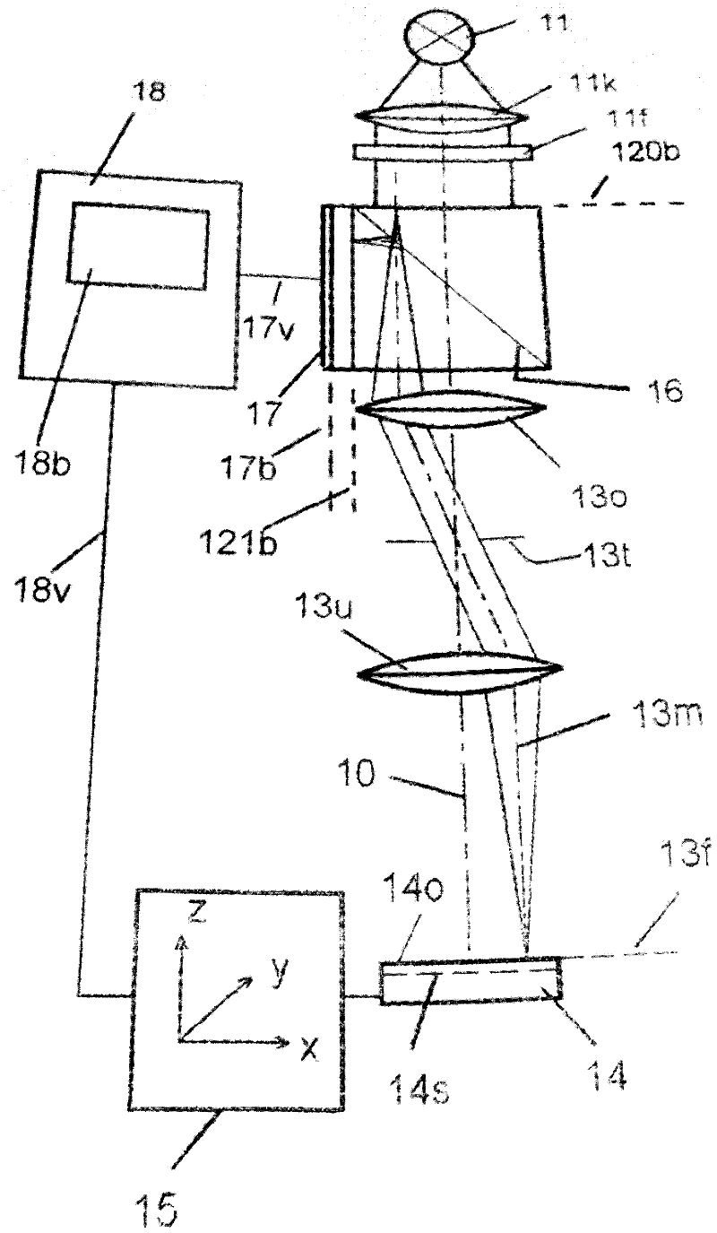
[0016] exist figure 1 Indicated by 11 is a light source, such as a halogen lamp, which emits light by means of a concentrator 11k, a hole in one layer. Such a layer can be produced in a known manner, for example from chromium on the glass plate 12g. The holes are arranged in the layer in a grid-like manner. For example layer 18 comprises pores of size eg 4 μm*4 μm. The size of the holes themselves is significantly smaller than their spacing.

[0017] The lighting grid created by the illuminated holes in the layer is located in the lighting plane 120b. This plane is projected by the lenses 13o, 13u into the focus plane 13f, so that the object 14 is illuminated in the focus plane by the light spots arranged in a grid.

[0018] For non-transparent objects only the surface 14o is illuminated, whereas for transparent objects the inner layer 14s can also be illuminated with light spots. The light rays reflected by the object in the focal plane 13 f are focused by the lenses 13 ...


PUM


Abstract

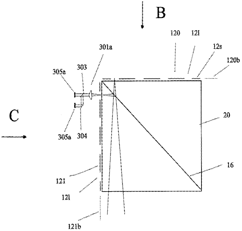
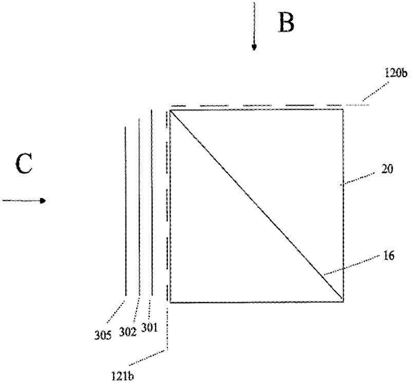
The present invention relates to a method and an apparatus used for researching a plurality of positions of an object and simultaneously performing fluorescence correlation spectroscopy, which can manufacture a required device with a low cost. The apparatus comprises a lighting grid (120b) having light emitting areas (121) for illuminating the object (14), and a lens assembly (13u), which indicates the lighting grid (120b) in a focal plane (14s) at location of the object (14); a perforated plate (121) provided on the receiver side. A mechanism (302a) is assigned to each hole (121) of the perforated plate of the observation beam path according to the focal plane for spectral segmentation of the light, and each mechanism (302a) used for spectral segmentation of the light is provided with at least two light receivers (305a).

Description

technical field [0001] The invention relates to a device or a method for examining an object by means of fluorescence correlation spectroscopy, which is used for simultaneous fluorescence correlation spectroscopy at a plurality of positions of an examination object and which enables cost-effective manufacture of the devices required for this purpose, with An illumination grating (Beleuchtungsraster) that illuminates the object and has a light-emitting area, an objective lens arrangement that projects the illumination grating into the focal plane at the object, and an aperture plate (Lochplatte) or aperture diaphragm (Lochblende) on the receiver side. Background technique [0002] In confocal microscopy, an object is illuminated in a known manner via an aperture diaphragm (Lochblende), and the illuminated point of the object is observed via a light receiver whose photosensitive surface is in contact with the illumination diaphragm formed by the illumination diaphragm. The bri...

Claims


Application Information

Patent Timeline
Patent Type & Authority Applications(China)
IPC IPC(8): G01N21/64G01J3/02G01J3/457
CPCG01J3/457G01N21/6456G01J3/0229G01J3/36G01J3/4406G01N21/6408
Inventor 鲁道夫.格罗斯科夫
Owner 鲁道夫.格罗斯科夫
Learn More