Electromagnetic radiation scanning and positioning method

An electromagnetic radiation, scanning and positioning technology, applied in the field of electromagnetic radiation scanning and positioning, can solve the problems that the electromagnetic radiation changes of the object under test cannot be dynamically displayed in real time, affect the sensitivity of electromagnetic radiation scanning equipment, and the scanning speed is slow, and achieve real-time two-dimensional electromagnetic radiation The effect of scanning positioning

Inactive Publication Date: 2012-07-11
SHANGHAI RADIO EQUIP RES INST
View PDF4 Cites 24 Cited by
  • Summary
  • Abstract
  • Description
  • Claims
  • Application Information

AI Technical Summary

Problems solved by technology

However, due to the characteristics of the microwave network structure of the current electromagnetic radiation scanning equipment, the measurement signal loss is large, which directly affects the sensitivity of the electromagnetic radiation scanning equipment
Its receiving equipment uses a standard spectrum analyzer, which has a slow scanning speed and cannot display the electromagnetic radiation changes of the object under test in real time and dynamically.
[0006] At present, electromagnetic radiation scanning equipment that can quickly scan electromagnetic radiation and display electromagnetic radiation distribution maps in real time has not been reported at home and abroad.

Method used


Image

  • Electromagnetic radiation scanning and positioning method
  • Electromagnetic radiation scanning and positioning method
  • Electromagnetic radiation scanning and positioning method

Examples


Embodiment Construction

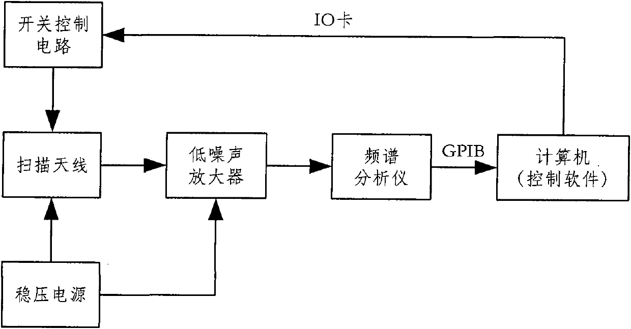
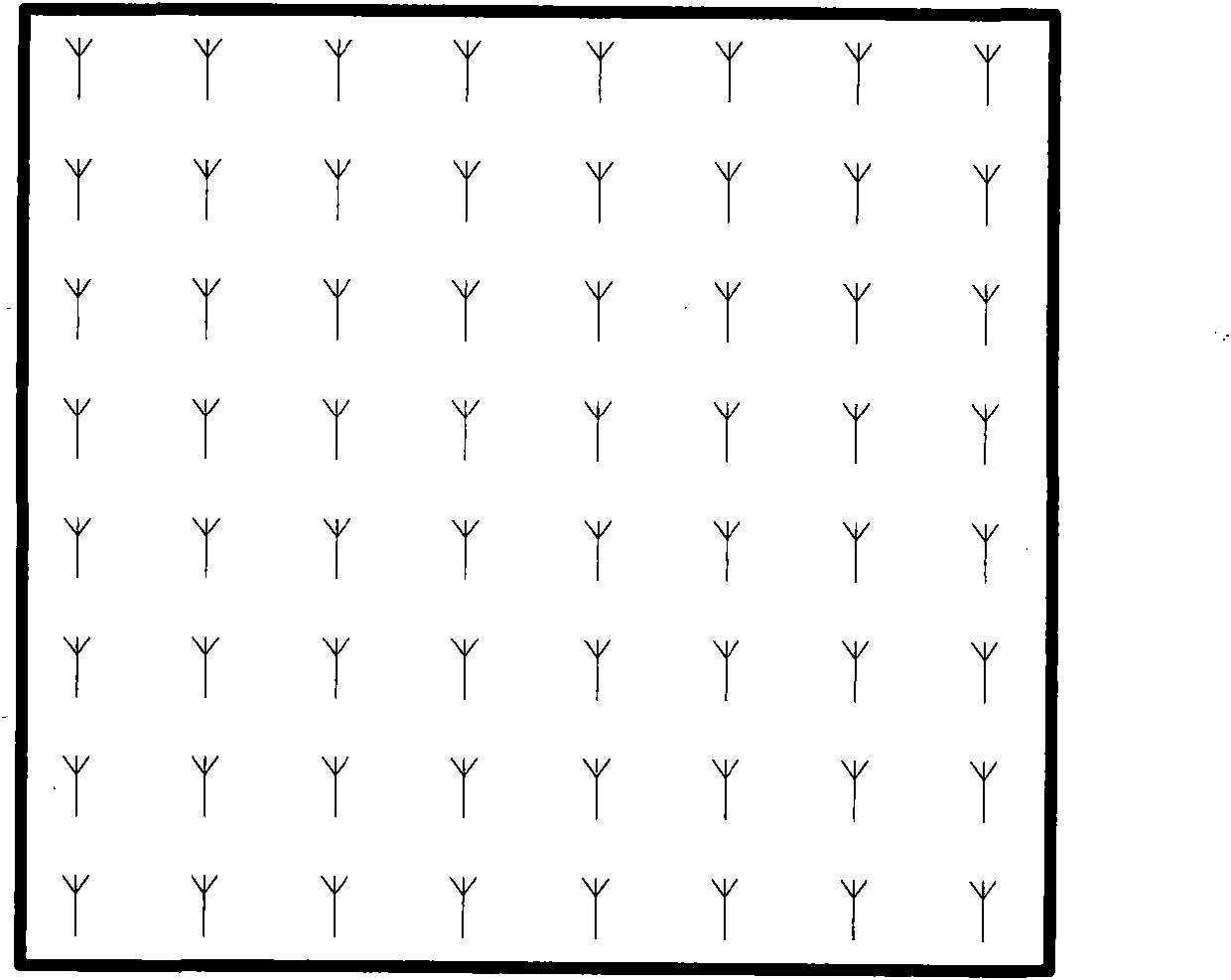
[0024] The electromagnetic radiation scanner is mainly composed of scanning antenna, pre-low noise amplifier, switch control circuit, regulated power supply, spectrum analyzer, control computer and related software. The block diagram of the system is as figure 1 shown. The scanning antenna is an array composed of a series of magnetic field probes. Each probe has an independent control switch. The top layer of the printed board is the antenna probe, the bottom layer is the switching circuit, the middle is the ground layer, and the top layer and the bottom layer are connected by metallization. hole connection. By switching the switches, the probes on the detection board can be arbitrarily selected, so that the signal on the probes can be detected by the receiver. In this way, by switching each switch in turn, the electromagnetic radiation intensity at each position on the circuit board can be detected and monitored. position. Magnetic field probe array diagram as figure 2 A...


PUM


Abstract

The invention relates to the technical field of electromagnetic radiation scanning and positioning, and aims to provide an electromagnetic radiation scanning and positioning method to replace the mechanical scanning technology, so that the electromagnetic radiation strength in each position of a circuit to be tested can be rapidly scanned and detected, a radiation source can be fixed, and continuous scanning and dynamic display can be realized. The method adopts an array type electromagnetic radiation detecting probe and the electronic switch technology, achieves unique spectrum and space scanning functions, and realizes the effects of scanning a selected area in a frequency range, and measuring the radiation circumstance of the whole frequency band in each special position of a tested object so as to obtain complete electromagnetic field information of the tested object. Data acquired by a scanning antenna under the control of electromagnetic scanning test software is subjected to fitting processing, so as to draw an electromagnetic radiation frequency spectrum and a spatial radiation cloud picture. The invention provides the method and equipment for the field of electromagnetic radiation measure, so as to quickly perform two-dimensional electromagnetic radiation scanning and positioning in a real-time manner.

Description

Technical field: [0001] The invention relates to the technical field of electromagnetic radiation scanning and positioning. Background technique: [0002] In the invention of electronic products, with the increase of the main frequency, the increase of the wiring density, the use of the multi-level scheme and the division technology of the ground plane and the power plane, there is a large amount of radiation interference between the signals in the PCB board, resulting in equipment malfunction or Work is unstable. [0003] Traditional tools for debugging PCBs to find circuit faults include oscilloscopes in the time domain, logic analyzers, and spectrum analyzers in the frequency domain, but these methods cannot provide data that reflects the overall information of the PCB. Time-domain equipment can only observe the time-domain waveform of one or a limited number of signals; frequency-domain equipment can only give the spectrum data of a frequency segment at a certain point....

Claims


Application Information

Patent Timeline
Patent Type & Authority Applications(China)
IPC IPC(8): G01R29/08G01R23/16
Inventor 韩非周顺满蒋继凤
Owner SHANGHAI RADIO EQUIP RES INST
Why Eureka
Try Eureka