Array plane layout method for space-borne SAR (Synthetic Aperture Radar) phased-array antenna

A technology of phased array antenna and layout method, which is applied in radio wave measurement system, radio wave reflection/reradiation, utilization of reradiation, etc., can solve the problem of reducing phased array antenna and achieve the effect of reducing influence

Inactive Publication Date: 2012-07-11
INST OF ELECTRONICS CHINESE ACAD OF SCI
View PDF2 Cites 14 Cited by
  • Summary
  • Abstract
  • Description
  • Claims
  • Application Information

AI Technical Summary

Problems solved by technology

[0005] The purpose of the present invention is to provide a phased array antenna array layout method for the limited scan problem of the existing phased array antenna, without increasing the

Method used


Image

  • Array plane layout method for space-borne SAR (Synthetic Aperture Radar) phased-array antenna
  • Array plane layout method for space-borne SAR (Synthetic Aperture Radar) phased-array antenna
  • Array plane layout method for space-borne SAR (Synthetic Aperture Radar) phased-array antenna

Examples


Embodiment

[0034] Taking the design of a typical spaceborne SAR active phased array antenna as an example, discuss the performance improvement after adopting the novel non-equidistant staggered array scheme of the method of the present invention, and compare it with the regular rectangular grid structure and the triangular grid structure array The surface layout schemes were compared.

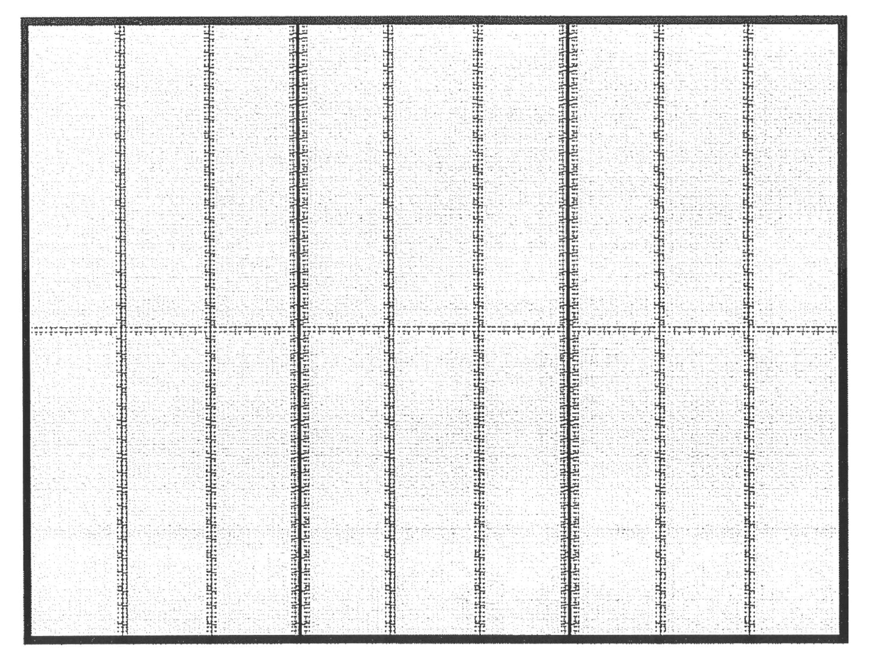
[0035] Assume that the spaceborne SAR active phased array antenna with a regular rectangular grid structure has an aperture size of 2800mm (distance direction) × 3600mm (azimuth direction), the operating frequency is X-band, and it is excited by 1152 T / R components. Among them, there are 128 T / R components in the distance direction, and each component excites a radiating unit; there are 9 T / R components in the azimuth direction, and each component excites 18 radiating units. Antenna front as figure 2 shown. The simulation results of the 1.5-degree center frequency normalized pattern in the azimuth scan...


PUM


Abstract

The invention discloses an array plane layout method for a space-borne SAR (Synthetic Aperture Radar) phased-array antenna and relates to a radar antenna technology. The array plane layout method comprises the following steps of: under the condition that the number of azimuth T/R (Transmit/Receive) assemblies (or phase shifters) of the phased-array antenna is not changed, dividing an array plane of the antenna into a plurality of unequal subarrays along the range direction; staggering along the azimuth direction of the antenna by using each subarray as the unit, wherein a staggering distance is about one second of a spacing of each two adjacent T/R assemblies in the range direction; and discretizing single big-peak scanning grating lobes of a regular rectangular lattice structure into a plurality of distributed small-peak grating lobes, so that the peaks of the scanning grating lobes in the azimuth direction are greatly reduced and the influence of the big-peak grating lobes on a radar system is reduced. The larger the number of the subarrays which have different spacings and are formed by dividing the antenna in the range distance is and the more the types of spacings between the subarrays are, the better the effect of discretizing the big-peak grating lobes is, however, the complexity of layout of a feed network of the phased-array antenna, the design of an antenna frame and the like are also increased. An array plane layout scheme suitable for the engineering application is obtained by comprehensively considering the complexity of the layout of the feed network and the design of the antenna frame and the effect of discretizing the scanning grating lobes in the azimuth direction.

Description

technical field [0001] The invention relates to the technical field of radar antennas, in particular to a space-borne SAR phased array antenna layout method. The method of the invention can be applied to a phased array radar antenna for limited scanning, can greatly reduce peak scanning grating lobes, and reduce the influence of large peak grating lobes on the azimuth ambiguity performance of a radar system. Background technique [0002] With the development of antenna technology and radar technology, a large number of modern high-performance radars, such as high-resolution synthetic aperture radar, adopt the phased array antenna system, and the application of active phased array antennas is becoming more and more extensive, and the antenna performance is getting better and better. The higher the cost, the lower the cost year by year. In the existing phased array radar applications, some high-performance radars use a fully distributed two-dimensional wide-angle scanning pha...

Claims


Application Information

Patent Timeline
IPC IPC(8): G01S7/42G01S13/90
Inventor 邓云凯孙慧峰赵凤军
Owner INST OF ELECTRONICS CHINESE ACAD OF SCI
Why Eureka
Try Eureka