A v-groove substrate
A V-shaped groove and substrate technology, applied in the direction of optical waveguide and light guide, to achieve the effect of small amount of grinding and polishing, low production and processing costs, and high control precision
- Summary
- Abstract
- Description
- Claims
- Application Information
AI Technical Summary
Problems solved by technology
Method used
Image
Examples
Embodiment Construction
[0019] Below by specific embodiment and in conjunction with accompanying drawing, the present invention is described in detail:
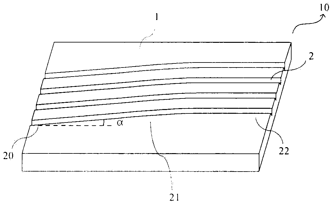
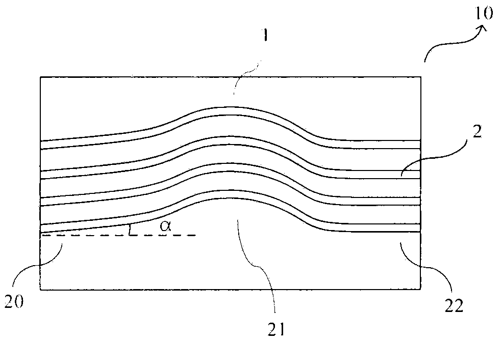
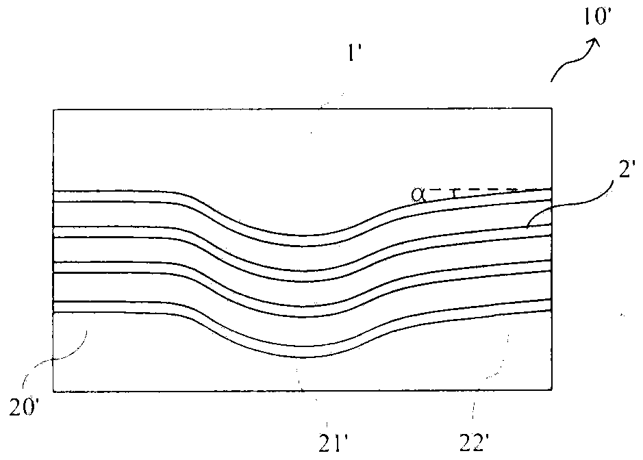
[0020] figure 1 It is a schematic diagram of an embodiment of the V-shaped groove substrate used for the output end of the waveguide chip after being made into an optical fiber array disclosed by the present invention. Such as figure 1 As shown, the V-shaped groove substrate 10 includes a substrate body 1 and a plurality of V-shaped grooves 2 located thereon, and the V-shaped groove 2 includes an input section 20 , a connecting section 21 and an output section 22 . The end surface of the substrate body 1 is perpendicular to the surface thereof, the V-shaped grooves 2 are arranged in parallel and the intervals between the V-shaped grooves are equal. The input section 20 of the V-shaped groove 2 is arranged in a straight line and forms an angle α with the normal line of the end surface of the substrate body 1 . In some embodiments, the deflection...
PUM
 Abstract
Description
Claims
Application Information
 - R&D
- Intellectual Property
- Life Sciences
- Materials
- Tech Scout
- Unparalleled Data Quality
- Higher Quality Content
- 60% Fewer Hallucinations
Browse by: Latest US Patents, China's latest patents, Technical Efficacy Thesaurus, Application Domain, Technology Topic, Popular Technical Reports.
© 2025 PatSnap. All rights reserved.Legal|Privacy policy|Modern Slavery Act Transparency Statement|Sitemap|About US| Contact US: help@patsnap.com


