Enhanced spi controller, enhanced spi communication system and data transmission method

A communication system and enhanced technology, which is applied in the field of serial communication, can solve the problems of inability to distinguish, inability to distinguish between valid data and invalid data, and inability to correctly distinguish valid and invalid data, etc., to achieve simple implementation, easy transplantation, and high transmission rate Improved effect

Active Publication Date: 2015-08-12
LEADCORE TECH
View PDF2 Cites 0 Cited by
  • Summary
  • Abstract
  • Description
  • Claims
  • Application Information

AI Technical Summary

Problems solved by technology

In the 2G era, the communication technology that uses the standard RS232 or UART interface to transmit data between the MODEM and the AP has been unable to meet the current wireless data transmission rate requirements in terms of rate.
This makes it impossible for the MASTER to determine which data is valid data sent after the T1 time period, and which data is invalid data sampled between T0 and T1
In the same way, when MASTER reads and accesses SLAVE, it also outputs the invalid data in the send FIFO buffer to the SDO data line at the same time, so that the SLAVE side cannot distinguish whether the data on its SDI data line is valid data or not. Invalid data, in short, in this communication mode, valid and invalid data on the SDO data line and SDI data line cannot be correctly distinguished, so true full-duplex data transmission cannot be achieved

Method used


Image

  • Enhanced spi controller, enhanced spi communication system and data transmission method
  • Enhanced spi controller, enhanced spi communication system and data transmission method
  • Enhanced spi controller, enhanced spi communication system and data transmission method

Examples


Embodiment Construction

[0041] The specific implementation manners of the present invention will be described in detail below in conjunction with the accompanying drawings.

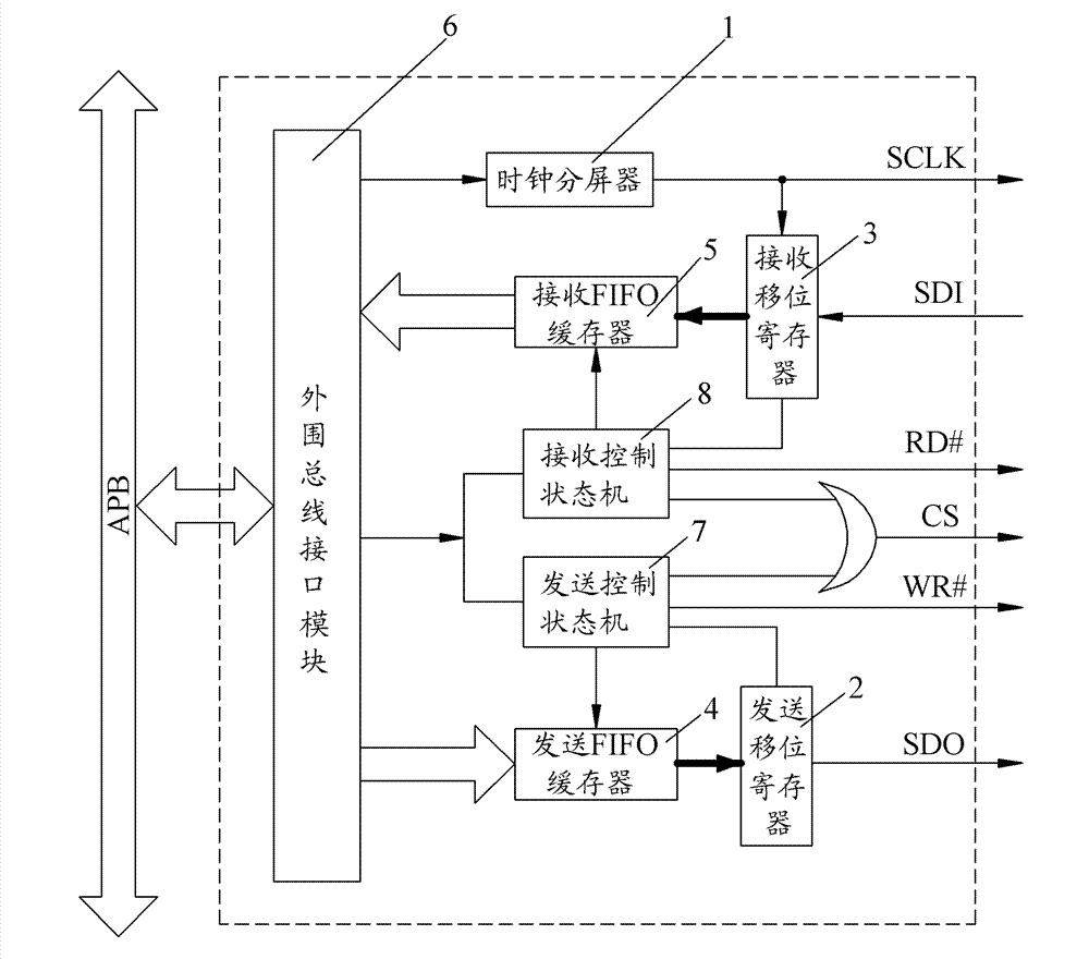
[0042] The present invention is based on the improvement of the existing SPI interface (bus) technology. Such as image 3 As shown, the functional block diagram of the enhanced SPI (abbreviated ESPI) controller of the present invention. As shown in the figure, the enhanced SPI controller includes: clock divider 1, sending shift register 2, receiving shift register 3, sending FIFO buffer 4, receiving FIFO buffer 5, bus interface module 6, by sending a write signal The transmission control state machine 7 used to control the data transmission of the enhanced SPI controller and the reception control state machine 8 used to control the data reception of the enhanced SPI controller by sending a read signal.

[0043] Wherein, the clock frequency divider 1 converts the clock signal input through the bus interface module 6 into a seri...


PUM


Abstract

The invention discloses an enhanced SPI (serial peripheral interface) controller, a communication system of the enhanced SPI and a data transmission method, and mainly aims at solving the problem that the existing SPI bus cannot actually realize full duplex. In the invention, a sending control state machine and a receiving control state machine are added to the existing SPI controller, wherein the sending control state machine independently controls the data sending of the enhanced SPI controller by sending a write signal; the receiving control state machine independently controls the data reception of the enhanced SPI controller through a read signal; or two control signals are added to the existing SPI interface method, namely a read signal RD# and a write signal WR#, and the sampling of an SDI signal and the sampling of an SDO signal of the SPI interface are triggered by the two signals, being equivalent to two independent state machines controlling the read and write. Through the enhanced SPI controller, the communication system of the enhanced SPI and the data transmission method, real full-duplex communication and high-speed data access are supported, and the control software is relatively easy to realize and convenient to transplant; and the enhanced SPI controller, the communication system of the enhanced SPI and the data transmission method are particularly suitable for the data communication between a high-speed MODEM (modulator-demodulator) and an AP (access point).

Description

technical field [0001] The invention relates to serial communication technology, in particular to an SPI interface (bus) technology. Background technique [0002] With the rapid development of wireless communication technology, especially the maturity of 3G technology, and the upcoming LTE broadband wireless communication technology, the uplink and downlink transmission rate of wireless data has increased rapidly, and the downlink transmission speed has reached the level of several M or even 100Mbps. The transmission speed has also reached the level of several M to tens of Mbps. In the 2G era, the communication technology that uses the standard RS232 or UART interface to transmit data between the MODEM and the AP has been unable to meet the current wireless data transmission rate requirements in terms of rate. At present, most 3G MODEMs and APs use USB interface technology or UART interface technology as the communication interface between 3G high-speed MODEMs and APs, but ...

Claims


Application Information

Patent Timeline
Patent Type & Authority Patents(China)
IPC IPC(8): G06F13/38
Inventor 史公正
Owner LEADCORE TECH
Why Eureka
Try Eureka