Embedded electrode frame of flow cell pile

An embedded electrode, flow battery technology, applied in the direction of fuel cell components, fuel cells, circuits, etc., can solve the problems of difficult production efficiency, production and assembly obstacles, complex structure and other problems

Active Publication Date: 2012-07-11
TSINGHUA UNIV +1
View PDF7 Cites 24 Cited by
  • Summary
  • Abstract
  • Description
  • Claims
  • Application Information

AI Technical Summary

Problems solved by technology

However, the structure is often too complicated, and it is difficult to completely solve the problems of electrolyte sealing and production efficiency in the stack manufacturing process, which hinders actual production and assembly

Method used


Image

  • Embedded electrode frame of flow cell pile
  • Embedded electrode frame of flow cell pile
  • Embedded electrode frame of flow cell pile

Examples


Embodiment 1

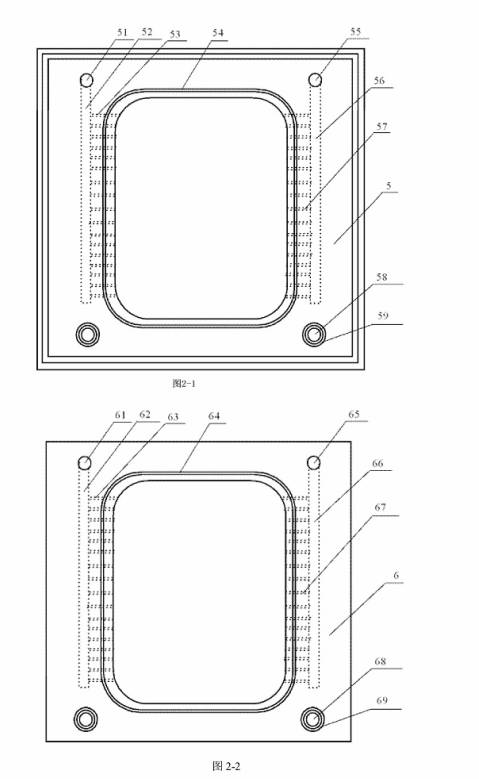
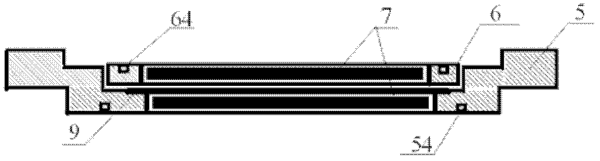
[0085] like image 3 Shown is the structure diagram of the I-type electrode frame.

[0086] The length and width of the first bipolar plate frame (5) are both 220 mm and 10 mm thick, and are made of polyvinyl chloride. The edge part is provided with double-layer grooves, the depth of the lower groove is 3mm, and the depth of the upper groove is 3mm. The height of the boss at the back is 4.5 millimeters, and an O-ring groove with a wire diameter of 2.4 millimeters is set on the periphery of the part where the electrode (7) is placed. The length and width of the second bipolar plate frame (6) are both 200 mm and 3.2 mm thick, and are made of polyvinyl chloride. A conductive plastic bipolar plate (9) with a thickness of 0.8 mm is placed between the first bipolar plate frame (5) and the second bipolar plate frame (6), and a polyvinyl chloride adhesive is used to The three are bonded to form an integral electrode frame (4) part, and electrodes (7) are placed in the electrode fra...

Embodiment 2

[0088] like Figure 4 Shown is the structure diagram of type II electrode frame.

[0089] The length and width of the first bipolar plate frame (5) are both 420 mm, and the thickness is 6.2 mm, made of polyvinyl chloride. The grooves are 1.5mm deep on the front and 1.5mm deep on the back. An O-ring groove with a wire diameter of 2.4 mm is arranged on the periphery of the part where the electrode (7) is placed on the front side. The length and width of the second bipolar plate frame (6) are both 400 mm and 3.2 mm thick, and are made of polyvinyl chloride. A conductive plastic bipolar plate (9) with a thickness of 0.6 mm is placed between the first bipolar plate frame (5) and the second bipolar plate frame (6), and a polyvinyl chloride adhesive is used to The three are bonded to form an integral electrode frame (4) part, and electrodes (7) are placed in the electrode frames of the first bipolar plate frame (5) and the second bipolar plate frame (6) to become The electrode fr...

Embodiment 3

[0091] like Figure 5 Shown is a structure diagram of a type III electrode frame.

[0092] The length and width of the first bipolar plate frame (5) are both 620 mm, and the thickness is 7 mm, made of polyvinyl chloride. The length and width of the front groove are 602 mm, and the depth is 3 mm. The length and width of the back boss are 588 mm, and the height is 2 mm. An O-ring groove with a wire diameter of 2.65 mm is arranged around the portion where the electrode (7) is placed on the first bipolar plate frame (5). The length and width of the second bipolar plate frame (6) are 600 mm, and the thickness is 4.7 mm. The length and width of the front groove are 590 mm, and the depth is 1.5 mm. It is made of polyvinyl chloride. A conductive plastic bipolar plate (9) with a thickness of 0.6 mm is placed between the first bipolar plate frame (5) and the second bipolar plate frame (6), and a polyvinyl chloride adhesive is used to The three are bonded to form an integral electrode...


PUM

PropertyMeasurementUnit
depthaaaaaaaaaa
thicknessaaaaaaaaaa
thicknessaaaaaaaaaa

Abstract

An embedded electrode frame of a flow cell pile belongs to the technical field of flow cell manufacturing. The embedded electrode frame is characterized in that a first bipolar plate frame (5) used as a positive pole half-cell of a single cell, a second bipolar plate frame (6) used as a negative pole half-cell of another adjacent single cell and a bipolar plate (9) clamped between the first bipolar plate frame (5) and the second bipolar plate frame (6) are connected sequentially to form an electrode frame (4). The first bipolar plate frame (5) and the second bipolar plate frame (6) achieve accurate location by means of a mutually embedded structure formed by a boss and a groove. A sealing ring groove provided with a sealing ring is arranged on the surface of the electrode frame which are formed by the first bipolar plate frame and the second bipolar plate frame, the sealing ring groove locates on the combined surface where the boss and the groove are in clamping connection to facilitate installation and sealing, and the flow cell pile is formed by connecting a plurality of electrode board frames.

Description

technical field [0001] An embedded electrode frame of a liquid flow battery stack belongs to the technical field of electrochemical energy storage, in particular to a technical method for manufacturing an electrode frame of a liquid flow battery stack. Background technique [0002] Using renewable energy such as wind energy and solar energy to generate electricity is one of the important ways for human beings to obtain energy from nature in the future. Due to the randomness and discontinuity of the wind and solar power generation process, it is difficult to maintain a stable power output. It needs to cooperate with a certain scale of power storage devices to form a complete power supply system to ensure continuous and stable power supply. Therefore, the development of energy storage systems with high power conversion efficiency, large storage capacity, and good economic performance has become the key to the development of renewable and clean energy. Among various forms of e...

Claims


Application Information

Patent Timeline
Patent Type & Authority Applications(China)
IPC IPC(8): H01M8/02H01M8/0273
CPCY02E60/50Y02P70/50
Inventor 王保国韩洪涛范永生成旭光陈晓宋世强
Owner TSINGHUA UNIV
Why Eureka
Try Eureka