Encapsulated stator assembly

A stator and component technology, which is applied to electric components, electrical components, magnetic circuit static parts, etc., can solve problems such as increasing the risk of thermal failure of motors

Inactive Publication Date: 2012-07-11
GENERAL ELECTRIC CO
View PDF4 Cites 7 Cited by
  • Summary
  • Abstract
  • Description
  • Claims
  • Application Information

AI Technical Summary

Problems solved by technology

Encapsulation of corrosion-sensitive components of the motor can thus increase the risk of thermal failure of the motor due to heating of metallic components experiencing elevated levels of eddy current losses
Various methods have been explored to reduce eddy current losses, but additional improvements are needed in order to produce more efficient electric drives

Method used


Image

  • Encapsulated stator assembly
  • Encapsulated stator assembly
  • Encapsulated stator assembly

Examples


Embodiment Construction

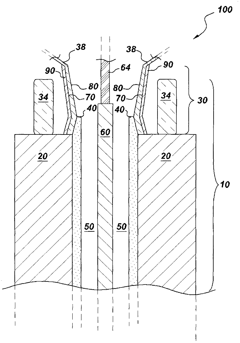
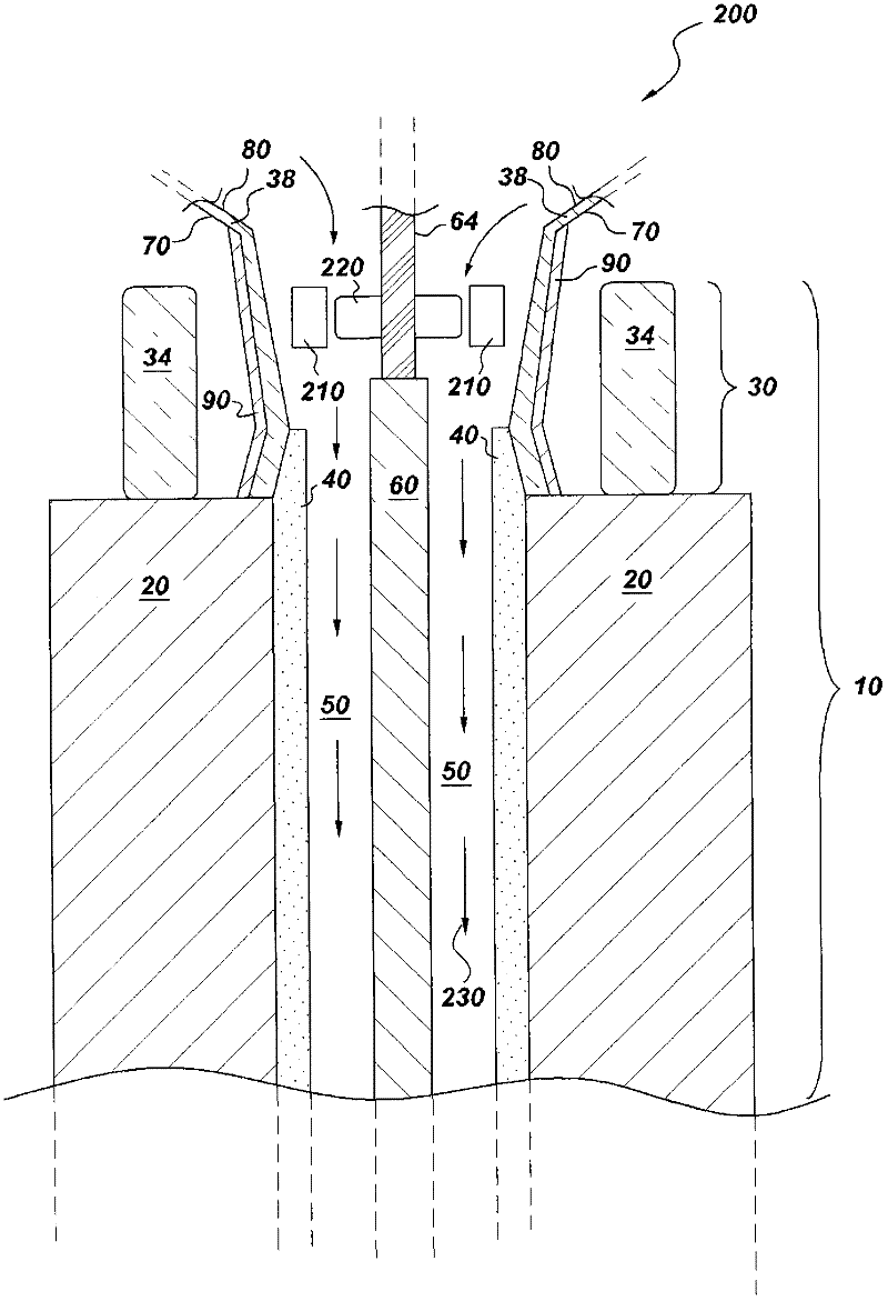
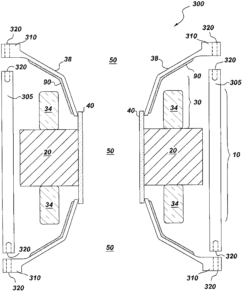
[0020] As noted, in one embodiment, the present invention provides an encapsulated stator assembly comprising: (a) a stator having a stator core and a stator end region; and (b) a ceramic bore tube, the ceramic bore tube defines a surface of the stator core; wherein the stator end region is disposed adjacent the stator core, and wherein the stator end region comprises a plurality of stator armature end windings, and wherein the stator end region comprises an inwardly facing stator wall, and wherein the ceramic bore tube and an inwardly facing stator wall define an interior volume configured to house the rotor, the inwardly facing stator wall having an inner surface and an outer surface, at least a portion of the inner surface comprising copper, silver and a barrier layer made of a conductive metal from the group consisting of aluminum, the inwardly facing stator wall contains a corrosion resistant metal.

[0021] The encapsulated stator assemblies provided by the present inven...


PUM


Abstract

The present invention provides an encapsulated stator assembly comprising: (a) a stator having a stator core and a stator end region; and (b) a ceramic bore tube defining a surface of the stator core; wherein the stator end region is disposed adjacent to the stator core, and wherein the stator end region comprises a plurality of stator armature end-windings, and wherein the stator end region comprises an inwardly-facing stator wall, and wherein the ceramic bore tube and the inwardly-facing stator wall define an interior volume configured to accommodate a rotor, said inwardly-facing stator wall having an inner surface and an outer surface, at least a portion of said inner surface comprising a barrier layer of a conductive metal selected from the group consisting of copper, silver and aluminum, said inwardly-facing stator wall comprising a corrosion resistant metal. Also provided are motors comprising the novel encapsulated stator assemblies.

Description

technical field [0001] The invention relates to a stator assembly for use in an electric drive machine. More particularly, the present invention relates to encapsulated stator assemblies for use in electric drive motors, such as those of compressors. Background technique [0002] In compressors that include an integral electric motor (integrated motor compressors), the electric drive motor is typically cooled by allowing process gas to flow through a portion of the motor. In cases where the process gas cannot be used as a coolant gas, for example when the process gas is a corrosive gas such as naturally occurring "sour gas", the motor must be properly isolated from the process gas and other cooling measures must be taken in order to cool the motor . [0003] Corrosion-resistant parts made of ceramic and / or corrosion-resistant metal alloys such as Inconel may be used to encapsulate sensitive parts of the motor, such as the motor stator. However, during operation, the motor...

Claims


Application Information

Patent Timeline
Patent Type & Authority Applications(China)
IPC IPC(8): H02K1/12H02K21/14
CPCH02K11/0005H02K5/128H02K3/42H02K11/014
Inventor C·M·斯蒂芬斯
Owner GENERAL ELECTRIC CO
Why Eureka
Try Eureka