Design method of filter at output end of frequency converter

A design method and output technology, applied in the filter field, can solve problems such as control failure, system program running out of control, equipment and production accidents, etc., to improve anti-interference ability and reliability, weaken additional torque, and weaken high-order harmonics The effect of wave components

Inactive Publication Date: 2012-07-11
XIAN KAIRONG ELECTRONICS TECH
View PDF0 Cites 3 Cited by
  • Summary
  • Abstract
  • Description
  • Claims
  • Application Information

AI Technical Summary

Problems solved by technology

The interference of the inverter system can sometimes directly cause damage to the hardware of the system, and sometimes it cannot damage the hardware of the system, but it often makes the system program of the microprocessor run out of control, resulting in control failure, resulting in equipment and production accidents

Method used


Image

  • Design method of filter at output end of frequency converter
  • Design method of filter at output end of frequency converter
  • Design method of filter at output end of frequency converter

Examples


Embodiment Construction

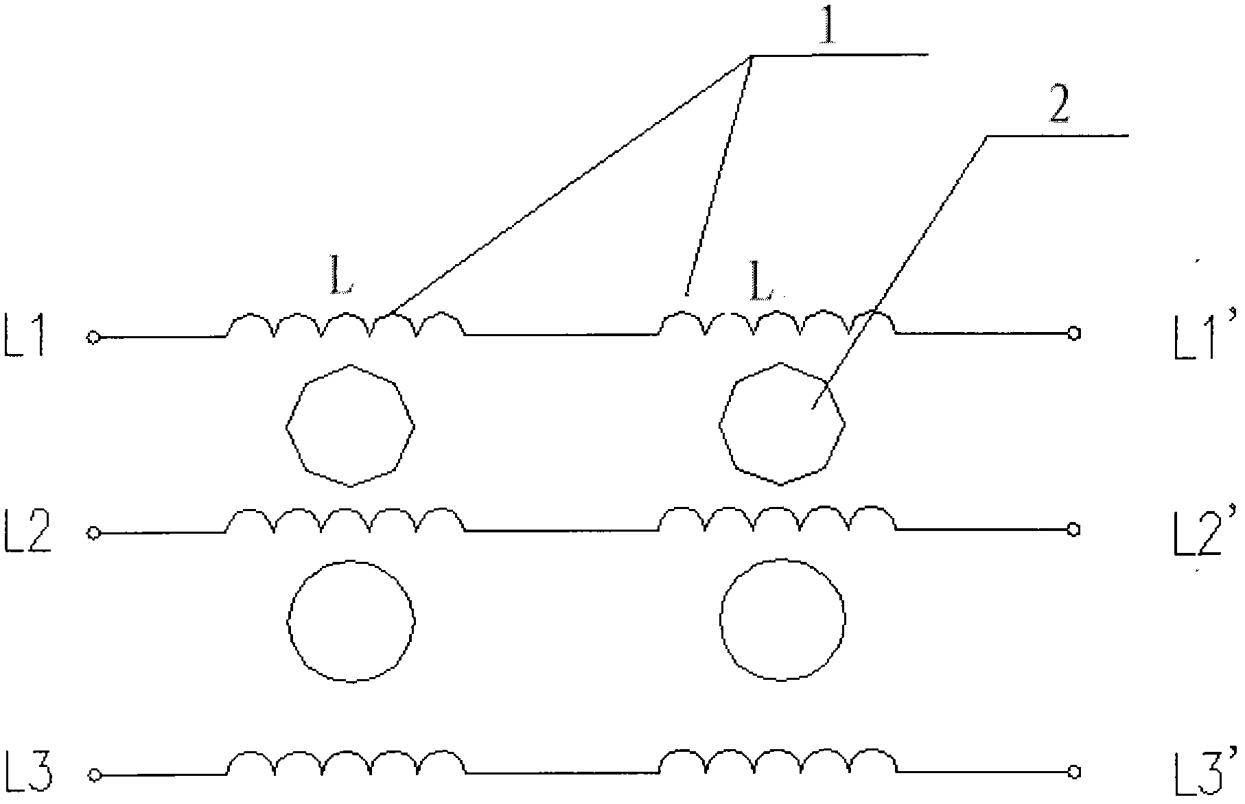
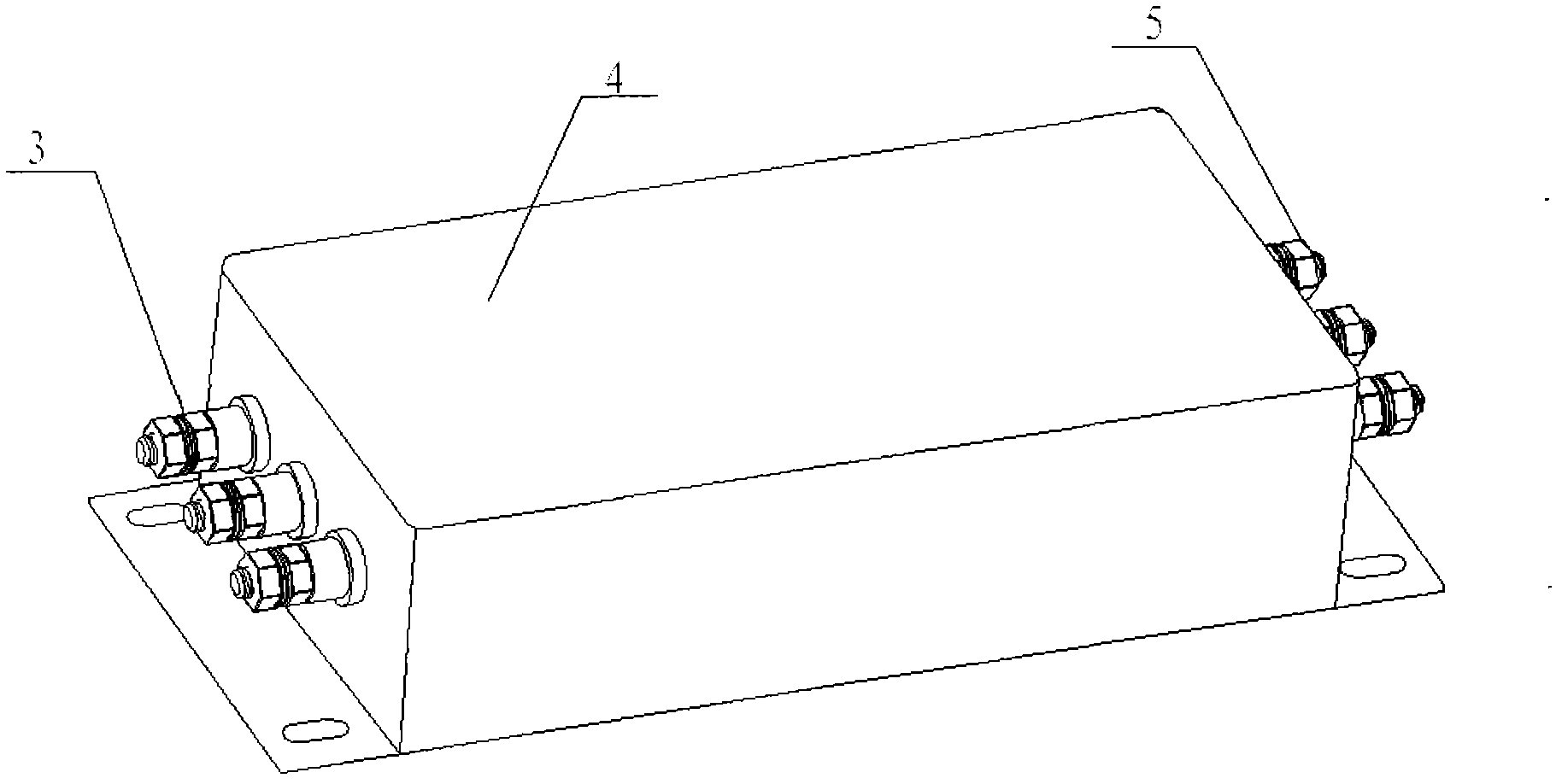
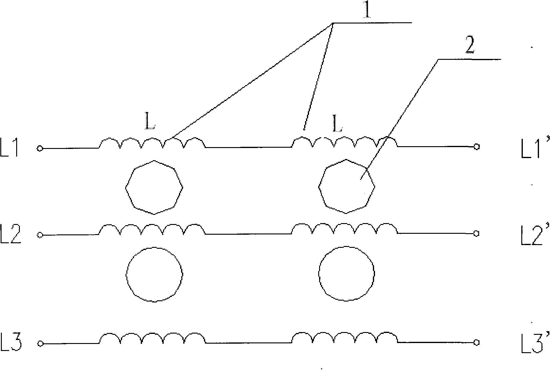
[0011] Such as figure 1 and figure 2 As shown, a design method for the filter at the output end of the frequency converter, including a nickel-plated shielding case 4 with a filter circuit, the filter circuit is installed inside the shielding case 4 with the filter circuit, and the filter circuit Including three groups, L1-L1', L2-L2', L3-L3', three groups of filter circuits L1-L1', L2-L2', L3-L3' are composed of two common mode inductors connected in series 1 electrical connection , the two common mode inductors 1 of each group are wound on the iron core 2 in common mode, the input of the three groups of filter circuits is electrically connected with the filter input terminal 3 on the side of the shielding shell 4, and the output of the three groups of filter circuits is connected with the shielding The filter output terminal 5 on the other side of the casing 4 is electrically connected. The input and output terminals of the filter adopt the common stud connection method, ...


PUM


Abstract

The invention relates to filter technology, in particular relates to a design method of a filter at an output end of a frequency converter. The filter comprises a shielding shell, wherein nickel is plated on the surface of the shielding shell, and three groups of filter circuits are arranged inside the shielding shell provided with the filter circuits. The design method is characterized in that each group of filter circuit comprises two serially-connected common mode inductors which are electrically connected, the two common mode inductors in each group of filter circuit are wound on an iron core in a common mode manner, input and output wiring terminals of the three group of filter circuits are fixed on two sides of the shielding shell provided with filter circuits by using insulation terminals; and the two common mode inductors of each group of filter circuit are connected in series to form a pure-inductance common mode filter network, and the common mode inductors are made of non-crystalline nano metal materials in a winding manner. According to the design method, influences and interference on normal working of a system due to electromagnetic conducting of the output end of the frequency converter through a cable are reduced.

Description

technical field [0001] The invention relates to a filter technology, in particular to a design method for a filter at the output end of a frequency converter. Background technique [0002] In the control system, with the widespread use of power electronic devices such as frequency converters, the electromagnetic interference (EMI) of the system is becoming more and more serious, and the corresponding anti-interference design technology (ie, electromagnetic compatibility EMC) has become more and more important. The interference of the inverter system can sometimes directly cause damage to the hardware of the system. Sometimes it cannot damage the hardware of the system, but it often makes the system program of the microprocessor run out of control, resulting in control failure, resulting in equipment and production accidents. Therefore, how to improve the anti-interference ability and reliability of the system is an important content that cannot be ignored in the development ...

Claims


Application Information

Patent Timeline
Patent Type & Authority Applications(China)
IPC IPC(8): H02M1/12H02M1/44
Inventor 邱扬张勃任琦
Owner XIAN KAIRONG ELECTRONICS TECH
Why Eureka
Try Eureka