Eureka AIR delivers breakthrough ideas for toughest innovation challenges, trusted by R&D personnel around the world.

Operational amplifier

A technology of operational amplifiers and operational amplifier circuits, applied in differential amplifiers, DC-coupled DC amplifiers, improved amplifiers to reduce nonlinear distortion, etc., can solve problems such as large nonlinearities, and achieve good linear transconductance and large voltage input dynamics range effect

Active Publication Date: 2012-07-11
CSMC TECH FAB2 CO LTD
View PDF5 Cites 8 Cited by
  • Summary
  • Abstract
  • Description
  • Claims
  • Application Information

AI Technical Summary

Problems solved by technology

[0005] The purpose of the present invention is to provide an operational amplifier to solve the problem of large nonlinearity caused by the input transconductance of the circuit structure changing with the input signal

Method used


Image

  • Operational amplifier
  • Operational amplifier
  • Operational amplifier

Examples


Embodiment approach

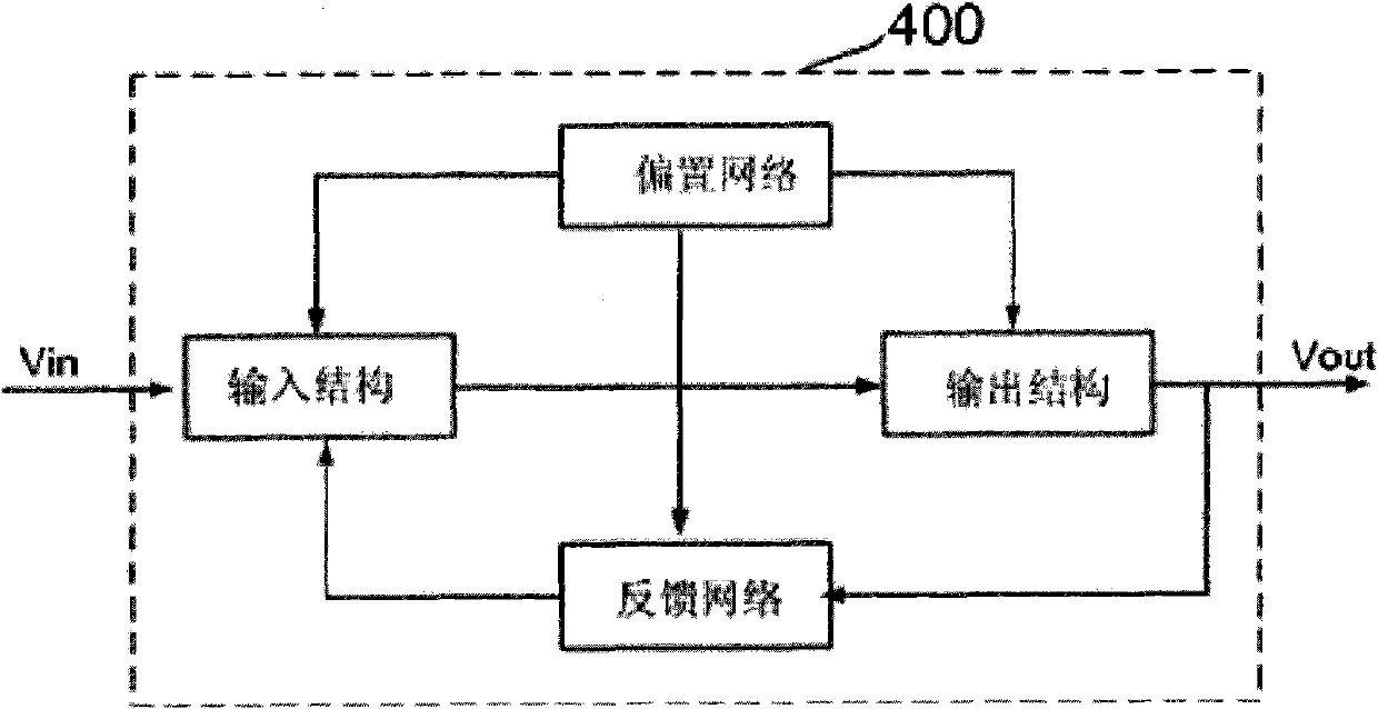
[0024] refer to figure 1 As shown, an implementation manner of the operational amplifier circuit of the present invention includes:

[0025] The input structure, which takes the signal and transmits the signal to the output structure;

[0026] The output structure amplifies the signal transmitted by the input structure;

[0027] Feedback network, which extracts the signal amplified by the output structure and feeds it back to the input structure;

[0028] The bias network simultaneously powers the input structure, the output structure, and the feedback network.

[0029] In the operational amplifier circuit of the above embodiment, the output signal of the output structure, that is, the output signal of the entire operational amplifier is monitored through the feedback network.

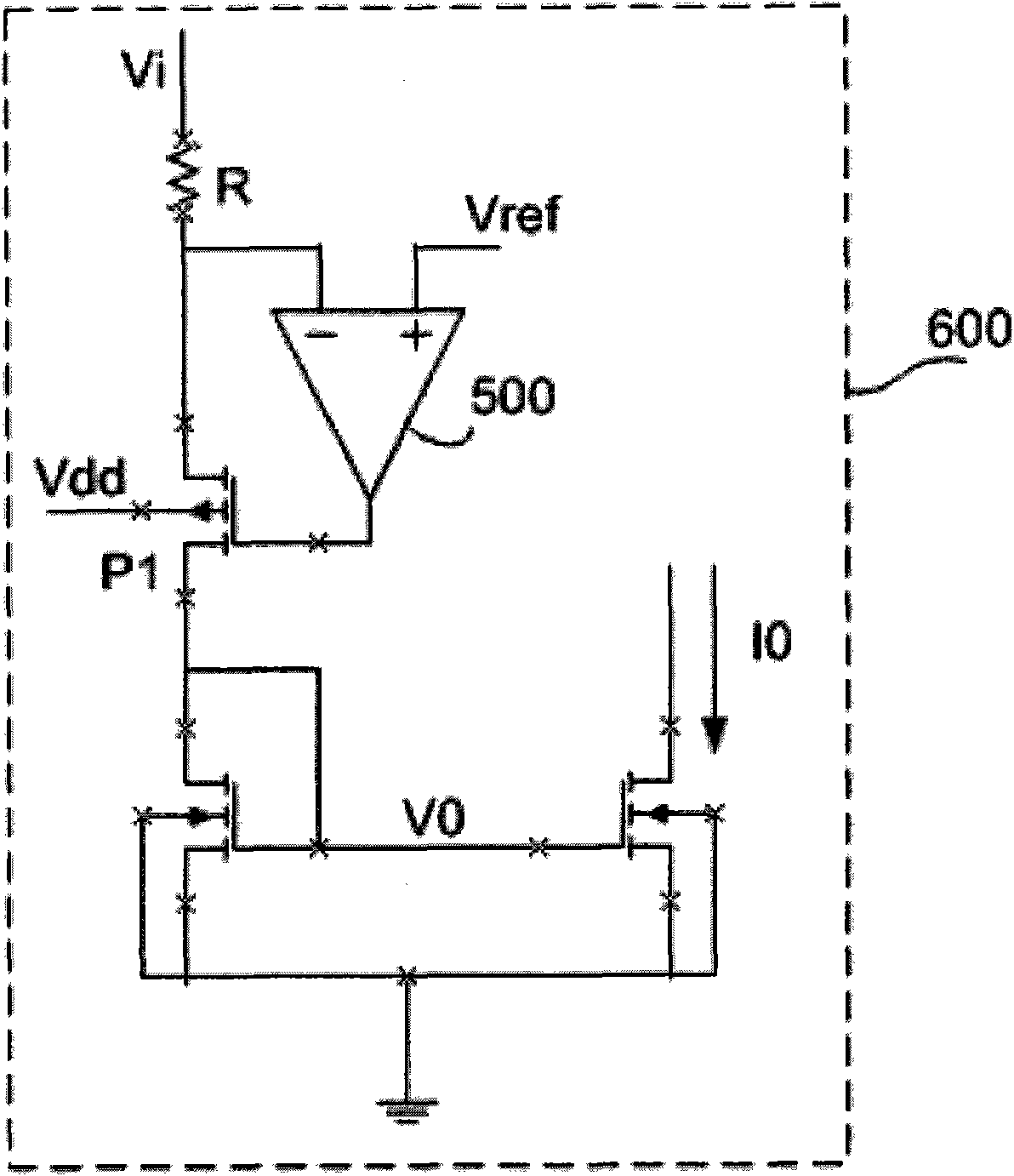
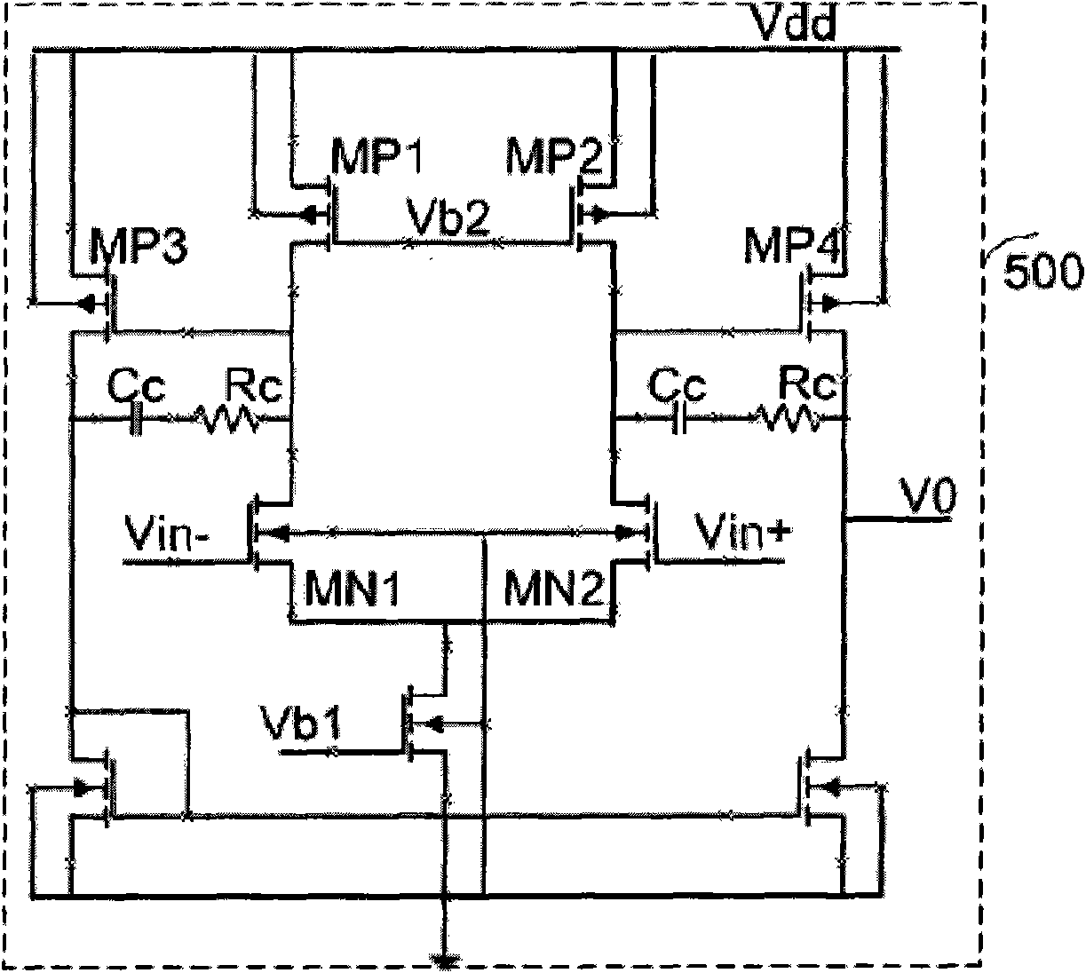
[0030] In the operational amplifier circuit, a low-voltage high-gain operational amplifier is used to clamp the potential of the input terminal, and ensure that the input voltage value of the input ...


PUM


Abstract

The invention provides an operational amplifier. The operational amplifier is characterized by comprising an input structure, a feedback network, an output structure and a bias network, wherein the input structure comprises an NMOS (N-channel metal oxide semiconductor) input operational amplifying circuit and a PMOS (P-channel metal oxide semiconductor) input operational amplifying circuit; the feedback network comprises an NMOS feedback loop connected with the NMOS input operational amplifying circuit and a PMOS feedback loop connected with the PMOS input operational amplifying circuit; the NMOS feedback loop and the PMOS feedback loop are used for ensuring the current of transistors to depend on the input voltage and the input end resistance under the condition that the input voltage Vi is greater or smaller than the reference voltage Vref; the output structure is used for amplifying signals transmitted by the input structure; and the bias network is used for supplying power to the input structure, the output structure and the feedback network simultaneously. The operational amplifier has the following beneficial effects: the reference voltage is set and the operational amplifier feedback loops with high gains are adopted; the current in the transistors has unipolarity, so good linear transconductance can be obtained; and meanwhile, a large dynamic voltage input range (from the ground to the power voltage) is realized.

Description

【Technical field】 [0001] The invention relates to the field of integrated circuit design, in particular to operational amplifier circuits. 【Background technique】 [0002] In semiconductor devices, operational amplifiers are widely used to amplify signals to be processed. An example of an operational amplifier is disclosed in Japanese Unexamined Patent Application Publication No. H6-326529 (US Patent No. 5,311,145). An operational amplifier includes an input stage amplifier and an output stage amplifier. The input stage amplifier converts the input signal according to the input structure of the output stage amplifier and amplifies the input signal. In addition, the input stage amplifier sets the no-load current that flows through the transistors that make up the output stage amplifier. The output stage amplifier amplifies the signal generated in the input stage amplifier and outputs the signal. [0003] As the size of MOS decreases, it is required to reduce the power supp...

Claims


Application Information

Patent Timeline
Patent Type & Authority Applications(China)
IPC IPC(8): H03F1/32H03F3/45
Inventor 李超
Owner CSMC TECH FAB2 CO LTD
Why Eureka
Eureka Blog
Learn More