Limited overturning dynamic logic circuit with scanning function

A dynamic logic and circuit technology, applied in the direction of logic circuits with logic functions, etc., can solve the problems of delay and large area overhead, and achieve the effect of small delay impact, small area overhead, and good logic measurability.

Inactive Publication Date: 2012-07-11
NAT UNIV OF DEFENSE TECH
View PDF3 Cites 3 Cited by
  • Summary
  • Abstract
  • Description
  • Claims
  • Application Information

AI Technical Summary

Problems solved by technology

At present, there are several implementation methods of LSDL logic that support the scanning function, but the existing methods generally have the disadvantages of delay and large area overhead

Method used


Image

  • Limited overturning dynamic logic circuit with scanning function
  • Limited overturning dynamic logic circuit with scanning function
  • Limited overturning dynamic logic circuit with scanning function

Examples


Embodiment 1

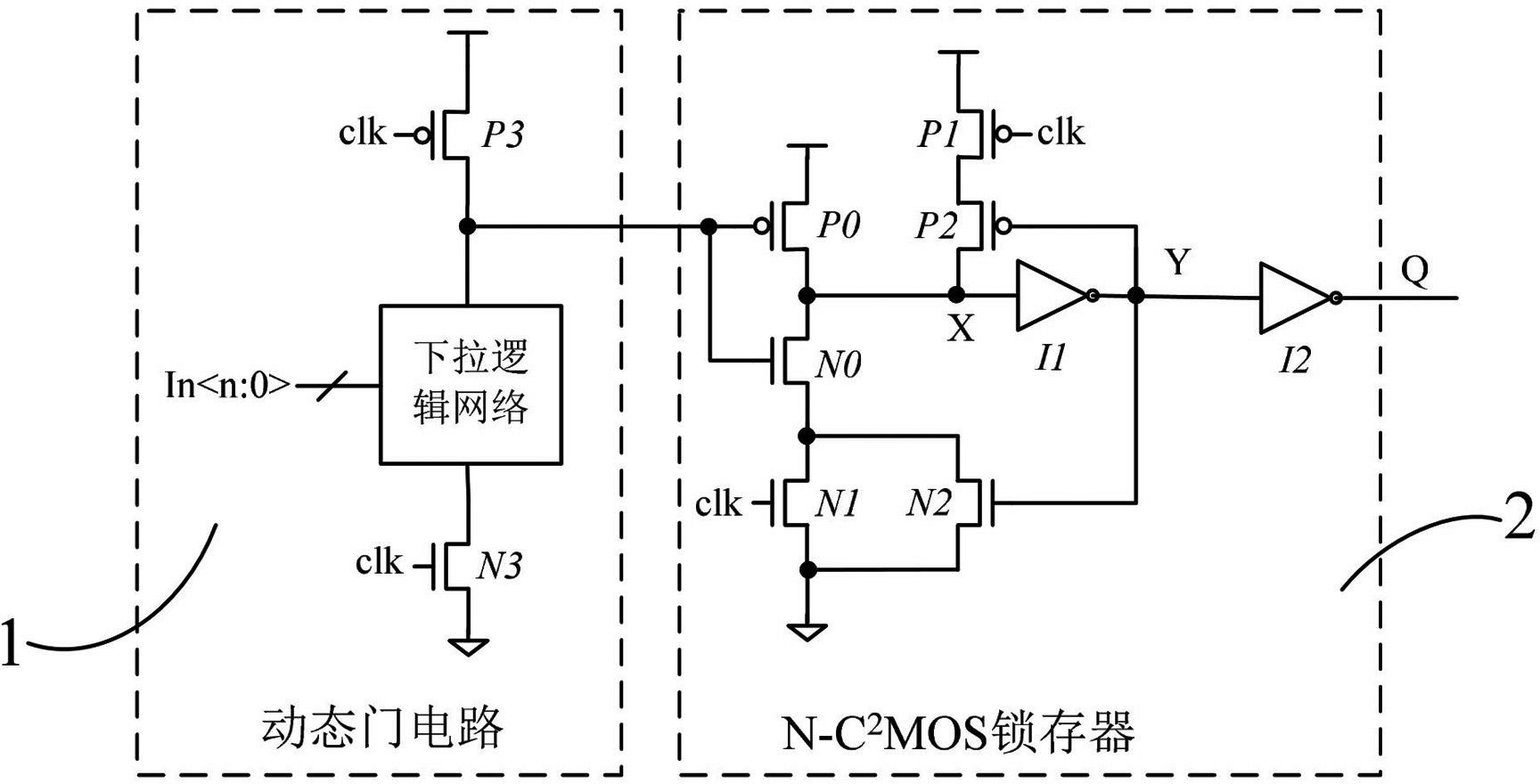
[0021] The present embodiment is the LSDL unit of the limited flip dynamic logic circuit with scan function, such as figure 2 As shown, the present embodiment includes peripheral modules and a LSDL core unit 8, and the LSDL core unit 8 includes dynamic gate circuits 1, N-C 2 MOS latch 2, scan enable input port SE, scan input port SI, scan output port SO, for sending the signal of the scan input port SI to the scan output port SO output when the scan enable input terminal SE input signal is valid The scan input logic 3, the peripheral module includes an enable control module 4 for closing the pull-down logic network 11 in the dynamic gate circuit 1 when the scan enable input terminal SE inputs a valid signal, and the input terminals of the scan input logic 3 are respectively connected to the scan enable The energy input terminal SE, the scan input port SI and the clock signal are connected, and the output terminal of the scan input logic 3 is connected to the N-C 2 The input ...

Embodiment 2

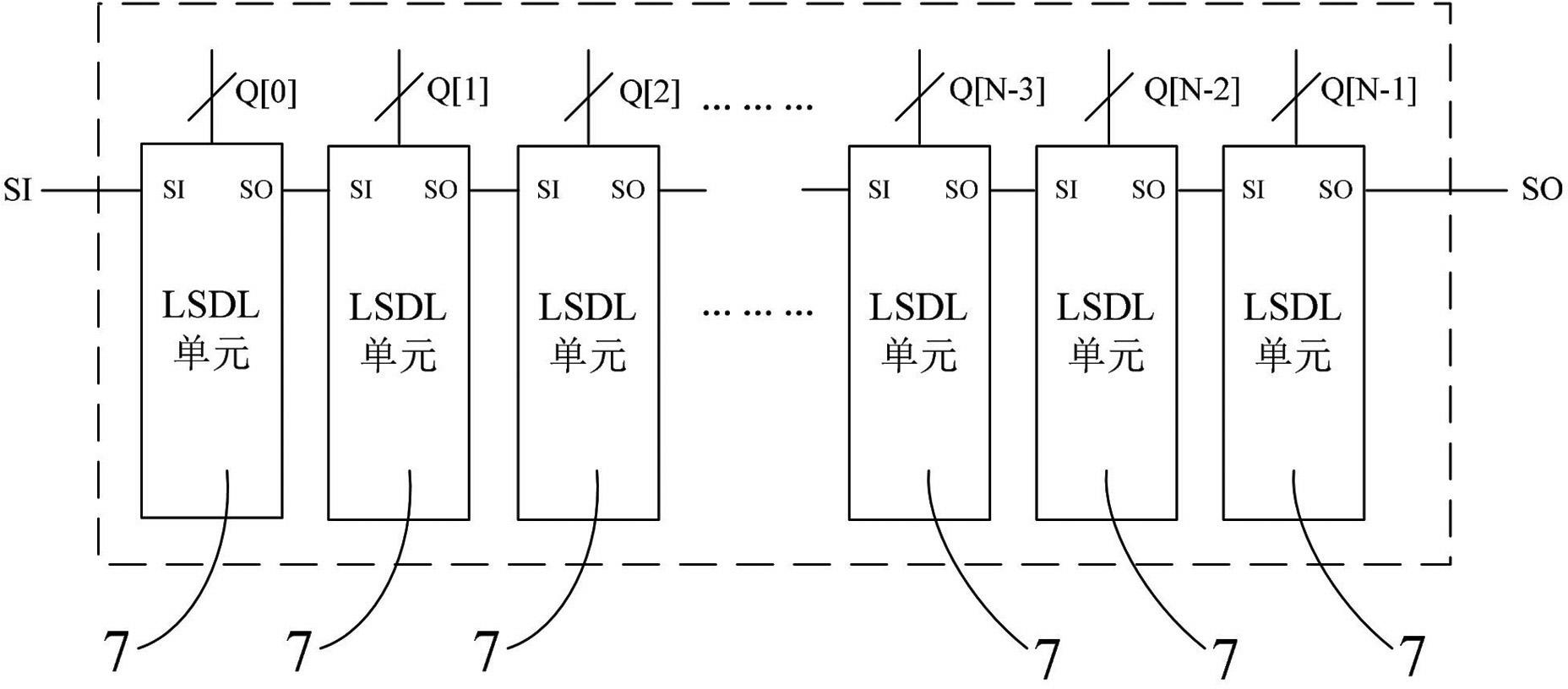
[0030] In this embodiment, a limited inversion dynamic logic scan chain circuit with a length of N and a scan function is formed by using a plurality of LSDL units in the first embodiment. This embodiment is basically the same as Embodiment 1, and the main difference is that this embodiment includes N independent LSDL units 7 , and each LSDL unit 7 includes one peripheral module and one LSDL core unit 8 . Such as image 3 As shown, the scan chain of length N constructed in this embodiment instantiates the LSDL unit 7 in Embodiment 1 as a whole N times, so that it includes N LSDL units 7 distributed in a chain, and the previous stage The scan output port SO of the LSDL unit 7 is connected to the scan input port SI of the next-level LSDL unit 7 , and so on, to form a scan chain with a length of N.

Embodiment 3

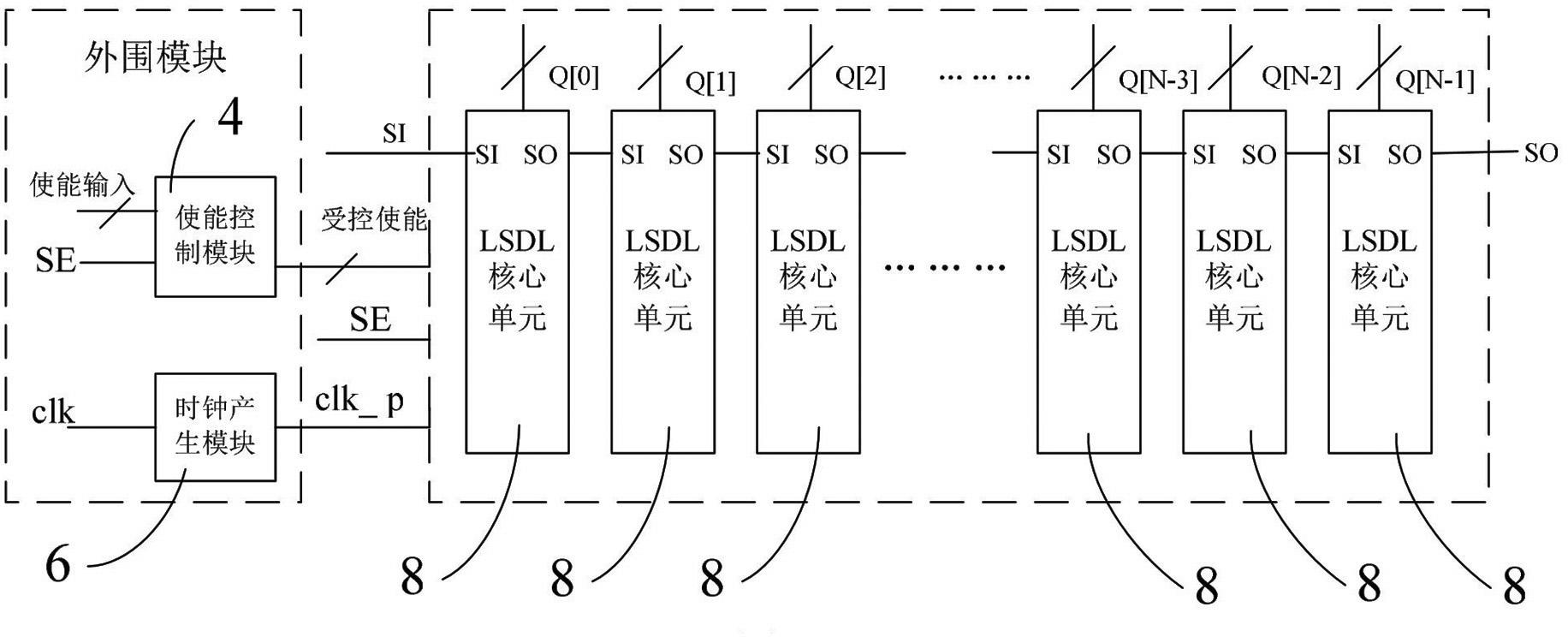
[0032] This embodiment is a limited flip dynamic logic scan chain circuit with a scan function and a length of N. This embodiment is basically the same as the first embodiment, and the main difference is that this embodiment includes one common peripheral module and N LSDL core units 8 . Such as Figure 4 As shown, the scan chain with a length of N constructed in this embodiment only connects N LSDL core units 8 in a chain-like distribution, and N LSDL core units 8 share one peripheral module, enabling the control module 4 and the clock generation module The output of 6 is used as a common signal to simultaneously drive N LSDL core units 8. This implementation method is suitable for designs with common enable inputs, and has the advantages of small area and low power consumption.


PUM


Abstract

The invention discloses a limited overturning dynamic logic circuit with a scanning function, which comprises a peripheral module and at least one LSDL core unit, wherein the LSDL core unit comprises a dynamic gate circuit, an N-C2MOS latch, a scanning enable input port, a scanning input port, a scanning output port and a scanning input logic device. The peripheral module comprises an enable control module, an input end of the scanning input logic device is respectively connected with the scanning enable input port, the scanning input port and clock signals, an output end of the scanning input logic device is connected with an input end of the N-C2MOS latch, and the scanning output port is connected with an output end of the N-C2MOS latch. An input end of the enable control module is connected with the scanning enable input port, and an output end of the enable control module is connected with a control end of a pull-down logical network. The limited overturning dynamic logic circuit has the advantages of good logic measurability, small time delay influence, small overall area expenses and low power consumption.

Description

technical field [0001] The invention relates to the field of high-speed dynamic gate circuit design of digital integrated circuits, in particular to a limited flip dynamic logic circuit with scanning function. Background technique [0002] like figure 1 As shown, the LSDL unit of the limited switching dynamic logic (Limited Switching Dynamic Logic: LSDL) circuit in the prior art can generally be divided into two stages: the first stage is a dynamic gate circuit 1, which is used for fast evaluation of multi-input complex logic ;Second level is an N-C 2 MOS latch 2. Dynamic Gate 1 and N-C 2 MOS latch 2 shares a clock, when dynamic gate 1 evaluates, N-C 2 MOS latch 2 is turned on, and the output data is updated; when the dynamic gate circuit 1 is precharged, N-C 2 MOS latch 2 is turned off and the output data is held. N-C 2 The MOS latch 2 has the functions of latching and amplifying at the same time, the utilization rate of the MOS tube is high, and the LSDL logic has t...

Claims


Application Information

Patent Timeline
Patent Type & Authority Applications(China)
IPC IPC(8): H03K19/20
Inventor 李振涛郭阳宋芳芳刘蓬侠陈书明刘祥远唐涛胡春媚张子杰付志刚王丽娟冯国柱邢冬生高维娜唐茜茜
Owner NAT UNIV OF DEFENSE TECH
Why Eureka
Try Eureka