HID (High Intensity Discharge) electronic ballast

A technology of electronic ballasts and resistors, applied in the field of HID electronic ballasts, can solve the problems of many components, poor linearity, complex frequency modulation and dimming circuits, etc., to increase the dimming circuit and dimming interface circuit, The effect of high reliability

Active Publication Date: 2012-07-11
宁波福至新材料有限公司
View PDF6 Cites 4 Cited by
  • Summary
  • Abstract
  • Description
  • Claims
  • Application Information

AI Technical Summary

Problems solved by technology

At present, many FM dimming circuits are very complicated, many components are used, and the linearity is not

Method used


Image

  • HID (High Intensity Discharge) electronic ballast
  • HID (High Intensity Discharge) electronic ballast
  • HID (High Intensity Discharge) electronic ballast

Examples


Embodiment Construction

[0026] The present invention will be further described in detail below in conjunction with the accompanying drawings and embodiments.

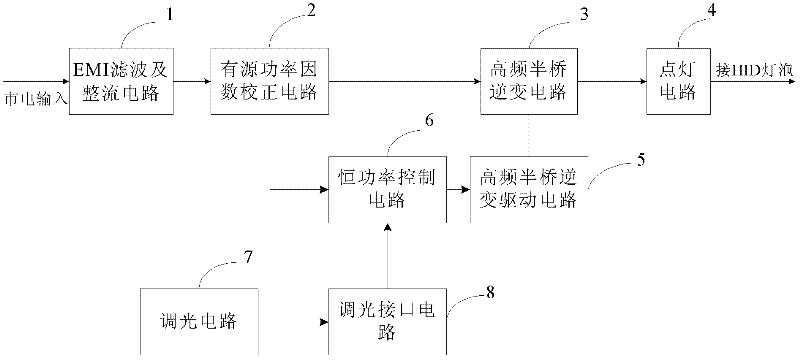
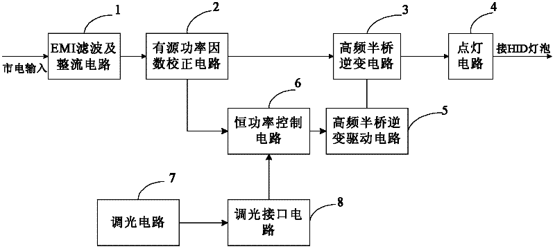
[0027] Such as figure 1 The HID electronic ballast shown includes EMI filter and rectification circuit 1, active power factor correction circuit 2, high-frequency half-bridge inverter circuit 3, lighting circuit 4, high-frequency half-bridge inverter drive circuit 5, constant The power control circuit 6, the dimming circuit 7 and the dimming interface circuit 8, wherein the input end of the EMI filter and rectification circuit 1 is connected to the mains, and is used to filter out radio frequency interference and electromagnetic interference from the mains, and attenuate electronic The radio frequency and electromagnetic interference generated inside the ballast make it reach a reasonable level, and convert the 90V-260V / 50-60HZ AC power from the mains into DC power for the active power factor correction circuit 2; the active power factor corre...


PUM


Abstract

The invention relates to an HID (High Intensity Discharge) electronic ballast, which comprises an EMI (Electro-Magnetic Interference) filtering and rectifying circuit, an active power factor correcting circuit, a high-frequency half-bridge inverter circuit, a lighting circuit and high-frequency half-bridge inversion driving circuit, and is characterized by further comprising a constant-power control circuit, wherein the input end of the constant-power control circuit is connected with the output end of the active power factor correcting circuit; the output end of the constant-power control circuit is connected with the high-frequency half-bridge inversion driving circuit; and the constant-power control circuit is used for acquiring current at the output end of the active power factor correcting circuit and outputting different control signals to the high-frequency half-bridge inversion driving circuit to adjust the working frequency of a control chip in the high-frequency half-bridge inversion driving circuit and realize correction and/or adjustment on the power of an HID bulb. Compared with the prior art, the HID electronic ballast has the advantages that: the constant-power control circuit is arranged, so that the HID electronic ballast provided by the invention has the characteristics of high reliability and capability of keeping stable work of the HID bulb.

Description

technical field [0001] The invention relates to a HID electronic ballast. Background technique [0002] The worldwide energy crisis in the 1970s led many companies to devote themselves to the research of new energy-saving electric light sources and AC electronic ballasts. The rapid development of semiconductor technology provides a prerequisite for the research and development of AC electronic ballasts. At the end of the 1970s, Philips of the Netherlands took the lead in developing the AC electronic ballast for fluorescent lamps, which was a major innovation in the history of the development of lighting appliances. The development of high-frequency AC electronic ballasts in my country began in the mid-1980s. At present, electronic ballasts for fluorescent lamps can be seen everywhere in the domestic market, and energy-saving lamps have already entered thousands of households; electronic ballasts for fluorescent lamps T4, T5, and T8 have been used in many domestic office bu...

Claims


Application Information

Patent Timeline
IPC IPC(8): H05B41/38
CPCY02B20/202Y02B20/00
Inventor 任忠平陈培国梁国锦
Owner 宁波福至新材料有限公司
Why Eureka
Try Eureka