Fixed type constant velocity universal joint

A constant velocity universal joint, fixed technology, applied in the direction of anti-centrifugal force rotating parts, elastic couplings, mechanical equipment, etc., can solve the problems of reducing ball contact force, reducing cage, reducing durability, etc. Effects of heat generation, cost reduction, and durability improvement

Active Publication Date: 2012-07-11
NTN CORP
View PDF5 Cites 7 Cited by
  • Summary
  • Abstract
  • Description
  • Claims
  • Application Information

AI Technical Summary

Problems solved by technology

Therefore, when the load on the joint is high or when the joint is rotated at a high speed, it becomes a main cause of heat generation of the joint, and the durability decreases.
[0014] In addition, in the constant velocity universal joint described in Patent Document 2, although the raceways are offset, the raceways of the inner and outer rings are helical or inclined in the axial direction, thereby reducing the amount of ball rolling on the raceways of the inner and outer rings. contact force, while reducing the force acting on the cage
However, even so, when a large load is applied to the joint or during high-speed rotation, heat may be generated due to the contact between the inner and outer spherical surfaces of the cage and the outer and inner spherical surfaces, reducing durability

Method used


Image

  • Fixed type constant velocity universal joint
  • Fixed type constant velocity universal joint
  • Fixed type constant velocity universal joint

Examples


Embodiment Construction

[0100] Below, based on Figure 1 to Figure 47 , to describe the embodiment of the present invention.

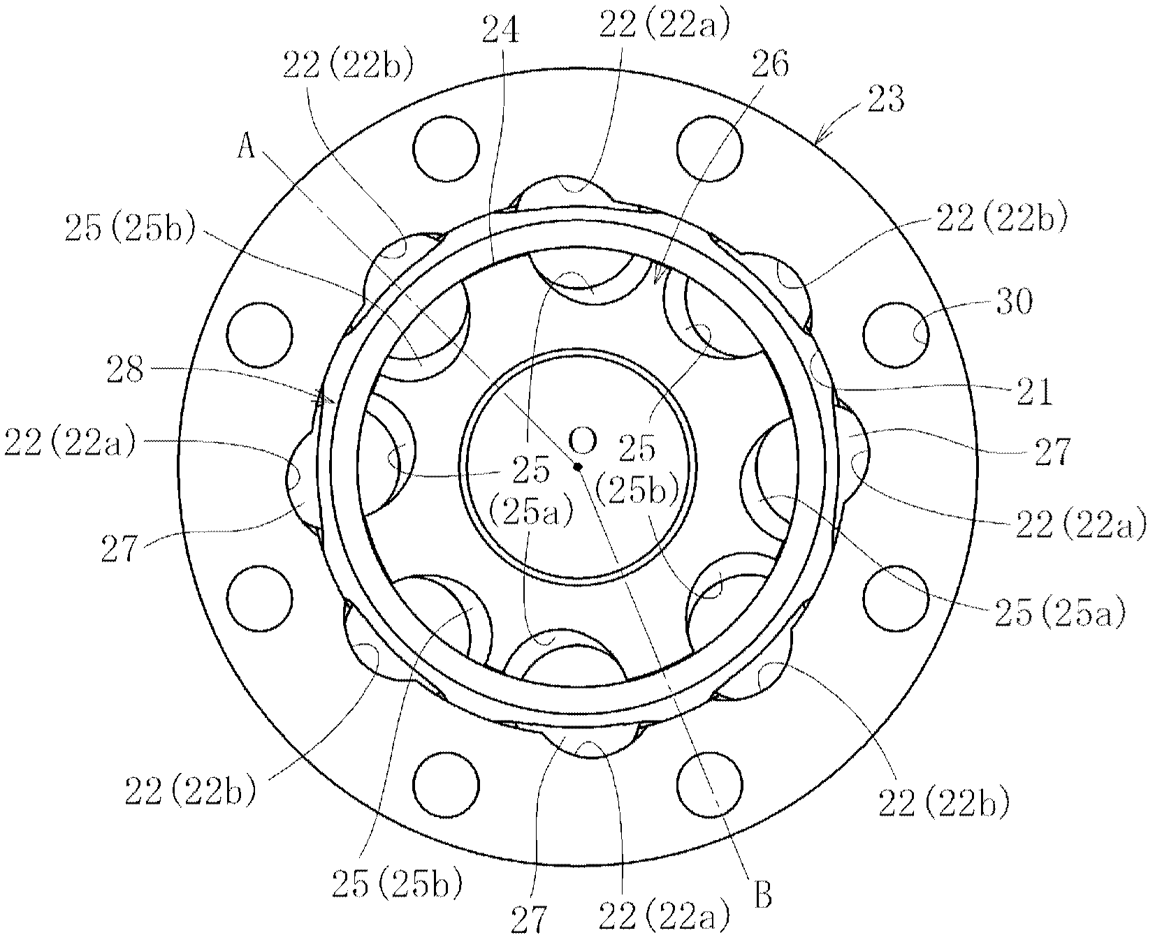
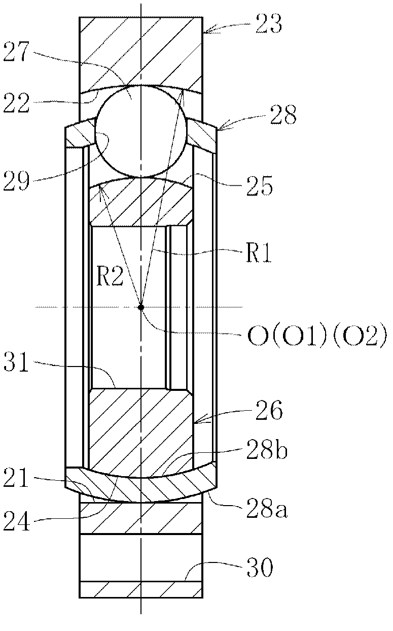
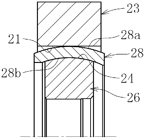
[0101] Such as figure 1 with figure 2 As shown, the fixed constant velocity universal joint according to the first embodiment of the present invention includes: an outer ring 23 as an outer joint member in which a plurality (eight) of raceway grooves 22 are axially formed on the inner diameter surface 21; On the outer diameter surface 24, a plurality of (eight) raceway grooves 25 are formed in the axial direction; an inner ring 26 as an inner joint member; A plurality (eight) of torque transmission balls 27 on ball raceways formed in pairs; and a cage 28 interposed between the inner diameter surface of the outer ring 23 and the outer diameter surface of the inner ring to hold the torque transmission balls.

[0102] The track groove bottom of the track groove 22 of the outer ring 23 is constituted only by a circular arc portion, and the center of curvature O1 thereof coin...


PUM


Abstract

Provided is a fixed type constant velocity universal joint wherein heat generation can be suppressed during high load operation or high speed rotation, resulting in improved durability, and wherein the contact resistance between the cage and the inner and outer races can be curbed, leading to improved constant velocity performance. The shaft direction offset of the center of curvature of a track groove (22) of an outside joint member and that of a track groove (25) of an inside joint member are zero. In the case of the outside joint member and the inside joint member, track grooves (22a, 22b, 25a, 25b), which are inclined reversely to each other with respect to the respective axes, are alternately formed in the circumferential direction. The outside diameter surface (24) of the inside joint member is a spherical surface which is in fitting contact with an inner spherical surface (28b) of the cage (28). The inside diameter surface (21) of the outside joint member is a cylindrical surface.

Description

technical field [0001] The present invention relates to a constant velocity universal joint used, for example, in a power transmission system of an automobile or various industrial machines. Background technique [0002] For example, a fixed type constant velocity universal joint is a type of constant velocity universal joint used as a mechanism for transmitting rotational force from an engine of an automobile to wheels at a constant velocity. This fixed constant velocity universal joint has a structure that connects two shafts of a driving side and a driven side, and transmits rotational torque at a constant speed even when the two shafts obtain an operating angle. In general, as the above-mentioned constant velocity universal joint, there are known a cage type (BJ) and an undercut type (UJ). [0003] Such as Figure 48 As shown, the BJ type fixed constant velocity universal joint has: an outer ring 3 as an outer joint member with a plurality of raceway grooves 2 formed on...

Claims


Application Information

Patent Timeline
Patent Type & Authority Applications(China)
IPC IPC(8): F16D3/224F16D3/20
CPCF16D3/223F16D2003/22303F16D3/224F16D3/2245F16D2003/22309Y10S464/906
Inventor 藤尾辉明杉山达朗
Owner NTN CORP
Why Eureka
Try Eureka