Non-invasive monitoring of blood metabolite levels

A metabolite, blood technology, applied in the field of non-invasive monitoring, can solve problems such as compensation difficulties

Inactive Publication Date: 2012-07-11
BIOSENSOR INC
View PDF8 Cites 5 Cited by
  • Summary
  • Abstract
  • Description
  • Claims
  • Application Information

AI Technical Summary

Problems solved by technology

Difficulties arise in compensating for these variations when attempting to determine biolo

Method used


Image

  • Non-invasive monitoring of blood metabolite levels
  • Non-invasive monitoring of blood metabolite levels
  • Non-invasive monitoring of blood metabolite levels

Examples


example 1

[0064] Example 1: Identification of organizational layers

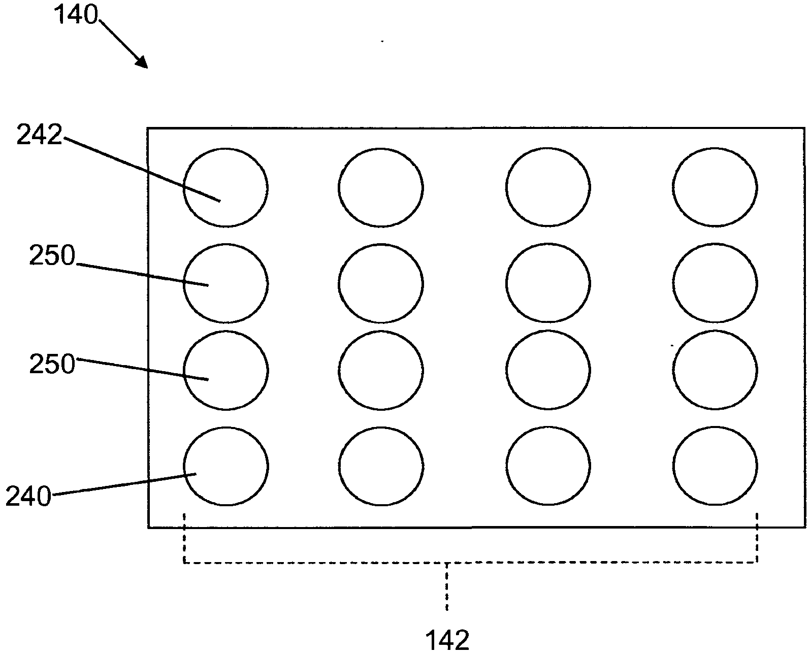
[0065] The following is achieved by using the Figure 4 An illustrative example of experimental results obtained with sensor array 143 of glucose monitor 140 . All sensors used in this experiment are disposable electrode( is a registered trademark of BIOPAC Systems, Inc., Goleta, California), and each electrode has a diameter of 10.5 mm. Figure 10 A schematic side view of the sensor array 143 as used in this experiment is shown. As described herein, each electrode in sensor array 143 is assigned a number (1-8). The sensor array 143 is configured such that the distance between the electrodes (center to center) is X and the distance from the center of electrode 1 to the center of electrode 8 is 7X (equal spacing between electrodes). In this example, measurements were obtained using a set of four electrodes, including one current-sending electrode, one current-receiving electrode, and two voltage-sensing electrod...

example 2

[0067] Example 2: Tissue Volume Removal

[0068] Figure 12 A conceptual model of the measured tissue volume and its measured impedance is shown. In this model, Z A representation mode A The measured impedance measure and volume of Z, and Z E representation mode E Measured impedance measurements and volumes of . In this test, the pattern E The distance between the electrodes in is the mode A Twice the distance between the electrodes in (2X to X). So, when starting from Z E Remove Z A The effect of (determining Z A and Z E difference between), Z1 is equal to Z A with Z A in series, so Z1=Z A +Z A (Equation 1 below). Z E is the parallel combination of Z1 and Z2, thus the parallel combination equation is Z E =(Z1Z2) / (Z1+Z2). Substitute into Z1 to get, Z E =(Z A +Z A )*Z2 / ((Z A +Z A )+Z2), where Z1 is the impedance value of the tissue from the surface to a depth of X and Z2 is the impedance value of the tissue from a depth of X to a depth of 2X. In one tes...

example 3

[0072] Example 3: Tissue volume differentiation

[0073]Further tests are performed to determine the difference between the readings from the patient's epidermis, and one of the dermis and subcutaneous layers. Electromagnetic impedance readings were measured from a standard sodium chloride solution of 140 mmol / L using sensor array 143 . Given the uniform volume of NaCl solution, it is empirically derived that at a single frequency each electrode pair ( Figure 11 ) between the measured volumes, whereby:

[0074] Z I =k IG Z G =k IC Z C (Equation 3)

[0075] Z G =k GC Z C (equation 4)

[0076] where Z is the measured mode ( I , G , C ) impedance and use 140mmol / L standard sodium chloride solution to calculate K IG 、K IC and K GC . To test whether these empirically derived relationships hold for animal tissues, two tests were done. Test A was performed on animal muscle tissue having a thickness of 35 mm, where the k value for homogeneous muscle ...


PUM

PropertyMeasurementUnit
The average thicknessaaaaaaaaaa

Abstract

Solutions for non-invasively monitoring blood metabolite levels of a patient are disclosed. In one embodiment, the method includes: repeatedly measuring a plurality of electromagnetic impedance readings with a sensor array from an epidermis layer of a patient and one of a dermis layer or a subcutaneous layer of the patient, until a difference between the readings exceeds a threshold; calculating an impedance value representing the difference using an equivalent circuit model and individual adjustment factor data representative of a physiological characteristic of the patient; and determining a blood metabolite level of the patient from the impedance value and a blood metabolite level algorithm, the blood metabolite level algorithm including blood metabolite level data versus electromagnetic impedance data value correspondence of the patient.

Description

[0001] Cross References to Related Applications [0002] This application is related in part to U.S. Patent Application No. 12 / 258,509, filed October 27, 2008, and U.S. Provisional Patent Application No. 61 / 185,258, filed June 9, 2009, which are incorporated by reference merged here. Background technique [0003] The present invention relates to the noninvasive monitoring of metabolite levels in a patient's blood. More specifically, the present invention relates to a solution for the non-invasive monitoring of metabolite levels in a patient's blood using sensor arrays and electromagnetic impedance tomography. [0004] Blood metabolite levels including glucose, lactate and hydration levels are important indicators of a patient's health and physical condition. In the non-invasive blood metabolite monitoring system, the measurement of biological data is performed on the surface (epidermal) of the patient's body. These superficial measurements are more sensitive to changes in t...

Claims


Application Information

Patent Timeline
IPC IPC(8): G01N27/02G01N33/49A61B5/00
CPCA61B5/14546A61B2562/0209A61B5/14532A61B2562/046A61B5/0531A61B5/1495
Inventor S·E·普鲁塔J·W·黑维特
Owner BIOSENSOR INC
Why Eureka
Try Eureka