Light-blocking member for use in optical equipment

A technology for optical equipment and components, applied in the field of light-shielding components for optical equipment, can solve the problems of reduced wear resistance, insufficient adhesion, and reduced content of light-shielding films, so as to reduce the amount of lubricant compounded and improve the adhesion. , the effect of improving heat resistance

Active Publication Date: 2012-07-11
KIMOTO CO LTD
View PDF7 Cites 4 Cited by
  • Summary
  • Abstract
  • Description
  • Claims
  • Application Information

AI Technical Summary

Problems solved by technology

As a result, first, there is a tendency to reduce the wear resistance of the light-shielding film due to a large amount of lubricant
Second, although the content of fine particles in the light-shielding film is not reduced, the light-shielding property is good, but the matting property cannot be fully expressed
However,

Method used


Image

  • Light-blocking member for use in optical equipment
  • Light-blocking member for use in optical equipment
  • Light-blocking member for use in optical equipment

Examples


Embodiment

[0072] Below, the present invention is further illustrated by examples. In addition, "part" and "%" are based on weight unless otherwise indicated.

[0073] 1. Fabrication of light-shielding parts for optical equipment

experiment example 1~19

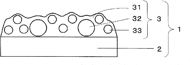
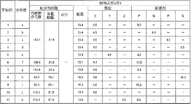
[0075] As a substrate, a polyimide film (Kapton 200H: Toray DuPont Co.) with a thickness of 50 μm was used, and the coating for a light-shielding film of the following formulation was coated on both sides by the bar coating method so that the thickness when dry was 10 μm. Liquids a to s were dried to form light-shielding films A to S, and light-shielding members for optical devices of each experimental example were produced. In addition, the content (part) of the acrylic polyol etc. of the coating liquid for light-shielding films of the following formulation is shown in Table 1, 2. Moreover, the content rate (%) of the acrylic polyol etc. of the light-shielding film formed is shown in Table 3, 4.

[0076]

[0077] ・Acrylic polyol (solid content 50%) (parts described in Table 1)

[0078] (Acrydic A804: DIC Corporation)

[0079] ・Isocyanate (solid content 75%) (parts described in Table 1)

[0080] (Burnock DN980: DIC Corporation)

[0081] ・Carbon black (parts described in ...

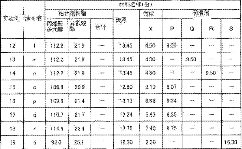
experiment example 12~19

[0133] About Experimental Examples 12-19, it is as follows.

[0134] In Experimental Example 19, the specific particulate lubricant used in Experimental Examples 12 to 18 was not used, and the content of the lubricant in the light-shielding film was high (16.30% by weight). As a relative effect, the adhesion could not be sufficiently improved. The content rate (64.8% by weight) of the agent resin. As a result, the adhesiveness and heat resistance of a light-shielding film are inferior. In addition, it was found that the adhesiveness and abrasion resistance of the light-shielding film tended to decrease as the weight ratio (lubricant / fine particle) in the light-shielding film increased (6.27).

[0135] In contrast, in Experimental Examples 12 to 18, since specific particulate lubricants were used, compared with Experimental Example 19, even if the content of the lubricant in the light-shielding film was reduced (16.30% by weight in Experimental Example 19), , Experimental Exa...


PUM

PropertyMeasurementUnit
Densityaaaaaaaaaa
The average particle sizeaaaaaaaaaa
Oil absorptionaaaaaaaaaa

Abstract

Provided is a light-blocking member for use in optical equipment. Said light-blocking member is highly slidable and also has the properties of a light-blocking film, such as opacity and matte properties. The provided light-blocking member also has improved wear resistance and adhesiveness. The light-blocking member (1) comprises a film substrate (2) and a light-blocking film (3) formed on at least one surface of the substrate. The light-blocking film (3) contains a binder resin, carbon black (31), a granular lubricant (32), and a particulate (33). The binder resin content is at least 65% by weight and the granular lubricant content is between 5% and 15% by weight. The density of the granular lubricant (32) is higher than the density of the particulate (33).

Description

technical field [0001] The present invention relates to a light-shielding member for optical equipment that can be used for shutters and aperture members of various optical equipment. Background technique [0002] In recent years, based on the miniaturization and weight reduction requirements of various optical devices such as high-performance SLR cameras, compact cameras, and video cameras, the shutter and aperture parts of optical devices formed of metal materials have gradually been converted to plastic materials. As a diaphragm made of such a plastic material, there is known a light-shielding film in which a light-shielding film containing carbon black, a lubricant, fine particles, and a binder resin is formed on a film base (Patent Documents 1 and 2). [0003] Patent Document 1: Japanese Patent Application Laid-Open No. 9-274218 [0004] Patent document 2: WO2006 / 016555 publication [0005] In the light-shielding film formed by the above-mentioned conventional method,...

Claims


Application Information

Patent Timeline
IPC IPC(8): G03B9/00B32B7/02B32B27/18G02B5/00G02B7/02G03B9/02G03B9/10
CPCG02B5/003G03B9/00Y10T428/31721B32B27/18G02B5/00G03B9/08
Inventor 高桥顺子原田正裕
Owner KIMOTO CO LTD
Why Eureka
Try Eureka