Overcurrent protection device and overcurrent protection system

一种保护装置、保护系统的技术,应用在紧急保护电路装置、电路装置、自动断开的紧急保护装置等方向,能够解决电源侧电压降低、电子开关不能正常工作等问题

Active Publication Date: 2012-07-11
YAZAKI CORP
View PDF7 Cites 11 Cited by
  • Summary
  • Abstract
  • Description
  • Claims
  • Application Information

AI Technical Summary

Problems solved by technology

[0003] In addition, when a dead short occurs in the load drive circuit, a counter electromotive force due to the impedance of the wiring is generated, resulting in a sharp drop in the voltage on the power supply side
Therefore, according to the method of detecting overcurrent based on the comparison result of the load current and the reference current, it may happen that when the power supply voltage drops to a voltage equal to or less than the operating range voltage of the operational amplifier, its overcurrent detection circuit itself cannot perform its function, Therefore, the electronic switch does not work properly in case of

Method used


Image

  • Overcurrent protection device and overcurrent protection system
  • Overcurrent protection device and overcurrent protection system
  • Overcurrent protection device and overcurrent protection system

Examples


Embodiment Construction

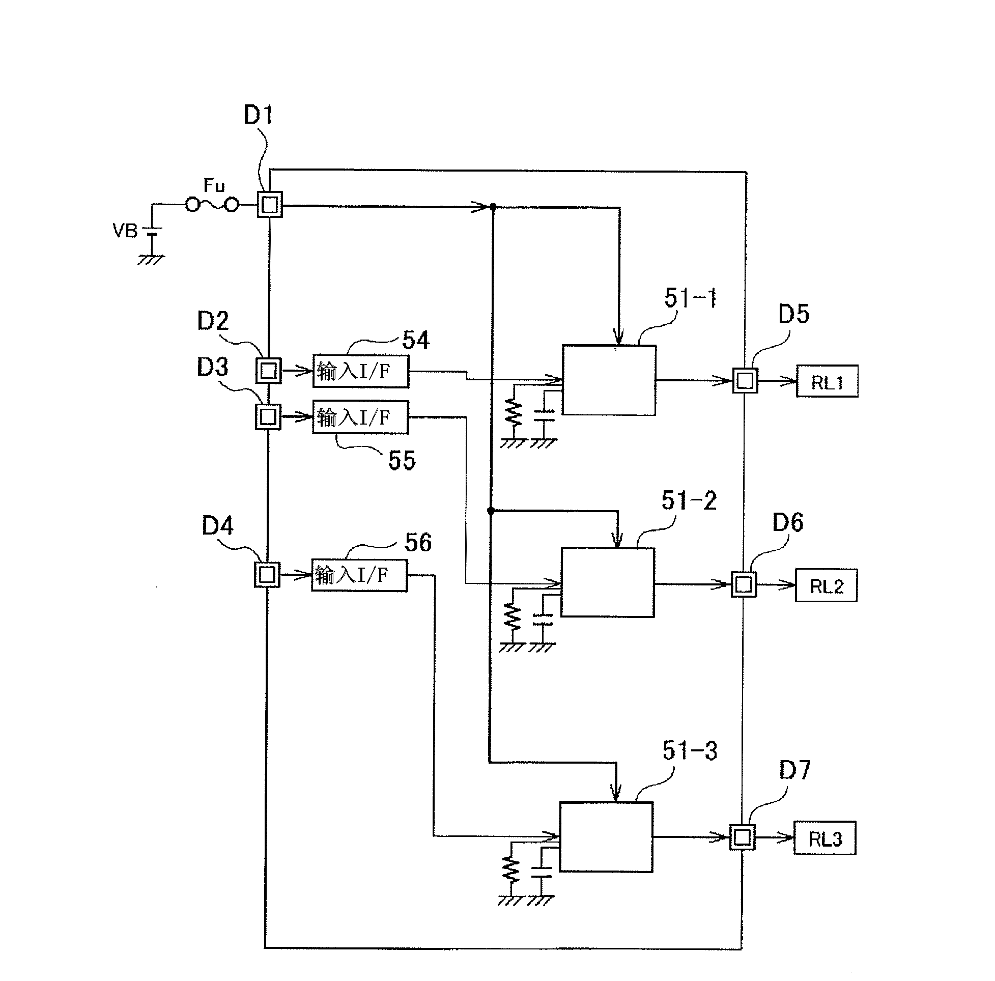
[0069] Embodiments of the present invention will be described below with reference to the drawings. figure 1 is a schematic diagram showing the configuration of an overcurrent protection system according to an embodiment of the present invention, which is installed, for example, in a load drive circuit for driving various loads RL (RL1 to RL3) such as light bulbs, motors, horns (the circuit consisting of VB, Q1a, RL1 and the wires connecting these elements), and has a disconnect load drive circuit when an overcurrent flows, thereby protecting the electronic switch (Q1a) and wires set in the circuit from Effects of overheating. Although this embodiment is described by taking a protection system for protecting three load driving circuits as an example, the number of circuits is not limited to three.

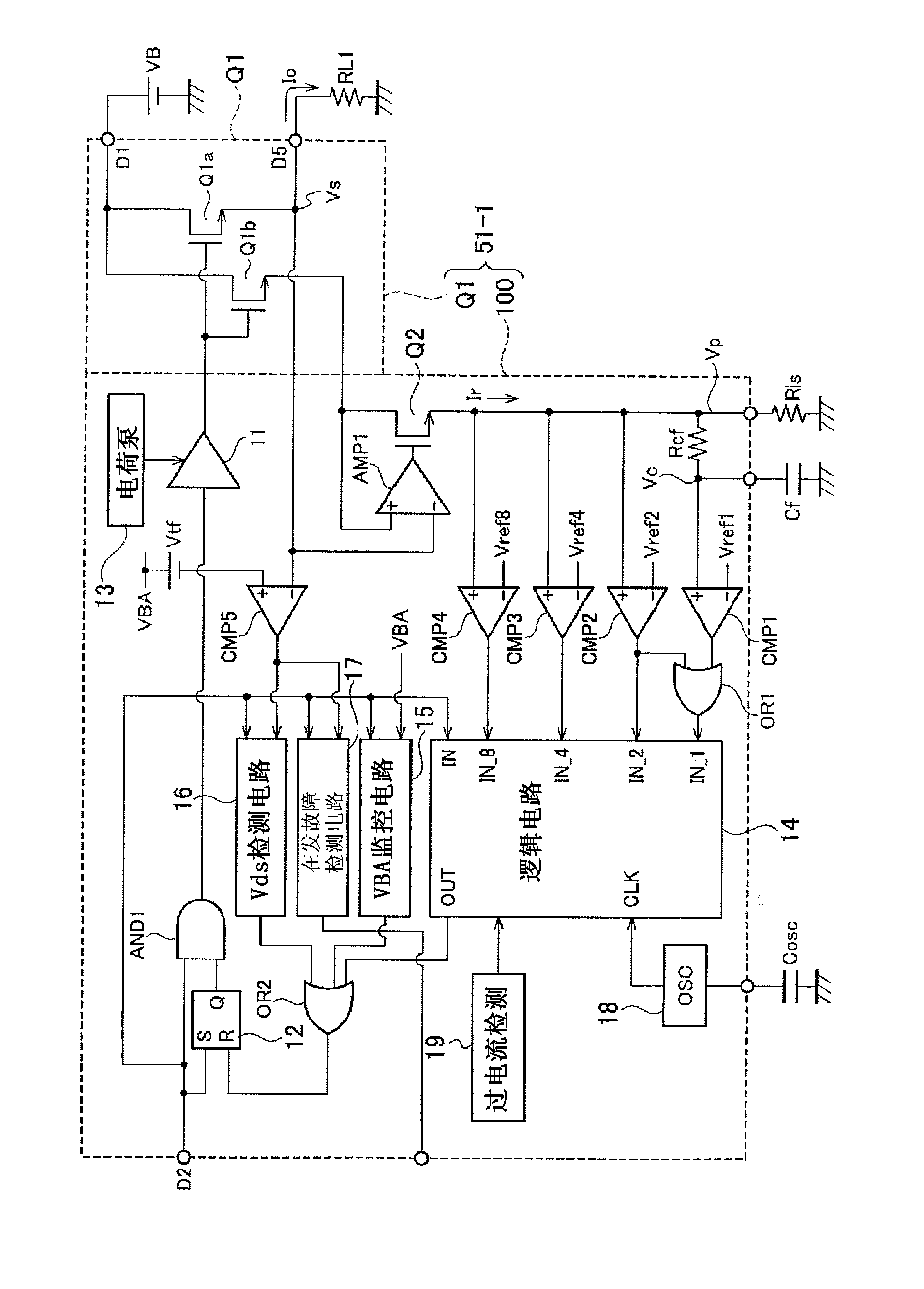
[0070] Such as figure 1 As shown, the overcurrent protection system includes three IC circuits 51-1 to 51-3. Each of the IC circuits 51-1 to 51-3 is connected to a battery (DC p...


PUM


Abstract

Provided are an overcurrent protection device and an overcurrent protection system which can provide time differences among the timings for executing the retry operations among a plurality of overcurrent protection devices connected to a common power supply. When a battery voltage (VBA) becomes a value equal to or lower than a threshold voltage after an FET (Q1) of an IC circuit (51-1) is turned on, all FETs (Q1) of the respective IC circuits are turned off, and a time until the battery voltage (VBA) reduces to a value lower than a threshold voltage after the turning-on of the FET (Q1) is clocked. When the time is smaller than 400 [mu]sec, the count value N is incremented. Further, turning-on of the FETs (Q1) is repeated after the lapse of the standby time (Tp) set randomly. When the count value N reaches 7, the FET (Q1) of the IC circuit (51-1) is held in the turned-off state. Accordingly, only the load-driving circuit at which the dead short occurs can be stopped and the driving of the other load-driving circuits can be continued.

Description

technical field [0001] The present invention relates to an overcurrent protection device and an overcurrent protection system. There are multiple overcurrent protection devices, and when an overcurrent flows through a load drive circuit composed of a load, an electronic switch and an electric wire, the The electronic switches of the load driving circuit are disconnected, thereby protecting the electronic switches and wires provided in the load driving circuit. Background technique [0002] For example, a load such as a light bulb or a motor mounted on a vehicle is connected to a battery through an electronic switch (for example, MOSFET), and its driving operation and stopping operation are controlled by switching the electronic switch between its on and off states. Furthermore, when a fault such as a short circuit occurs on the load, and thus an overcurrent flows through the load drive circuit, the load and the connection harness may be damaged due to heat generation. There...

Claims


Application Information

Patent Timeline
Patent Type & Authority Applications(China)
IPC IPC(8): H02H3/087B60R16/03
CPCH02H3/087H02H3/066H02H3/07
Inventor 长沢一美栗田薰中山雅之远山一郎前田光章石间茂巳
Owner YAZAKI CORP
Why Eureka
Try Eureka