
Tea leaf rolling device capable of realizing continuous feeding and discharging

A rolling device, feeding and discharging technology, applied in the field of tea processing equipment, can solve the problems of poor rolling effect, low work efficiency, slow conveying speed, etc., and achieve the effects of fast rolling speed, improved production efficiency, consistent pressure and time

Active Publication Date: 2012-07-18
ZHEJIANG ZHUFENG MACHINERY
View PDF5 Cites 16 Cited by
  • Summary
  • Abstract
  • Description
  • Claims
  • Application Information

AI Technical Summary

Problems solved by technology

In specific implementation, this technical solution has the following problems: due to the tea kneading area in the annular space area formed between the outer cylinder and the inner cylinder, its space is narrow and small, the amount of tea leaves kneaded is very small, and the delivery speed of the tea leaves is very slow , the working efficiency is low. During the work, due to the slow rolling speed, it is often necessary to stop feeding; the inner and outer cylinders are at a certain inclination angle to the installation ground plane, and the tea leaves enter from the tea inlet. Part of the gravity effect of the tea leaves will advance along the longitudinal direction of the kneading barrel in the kneading area, so that the kneading effect is poor due to the absence of other auxiliary pressure.

Method used


Image

  • Tea leaf rolling device capable of realizing continuous feeding and discharging
  • Tea leaf rolling device capable of realizing continuous feeding and discharging

Examples


Embodiment Construction

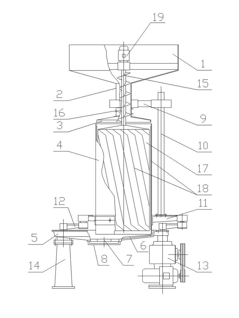
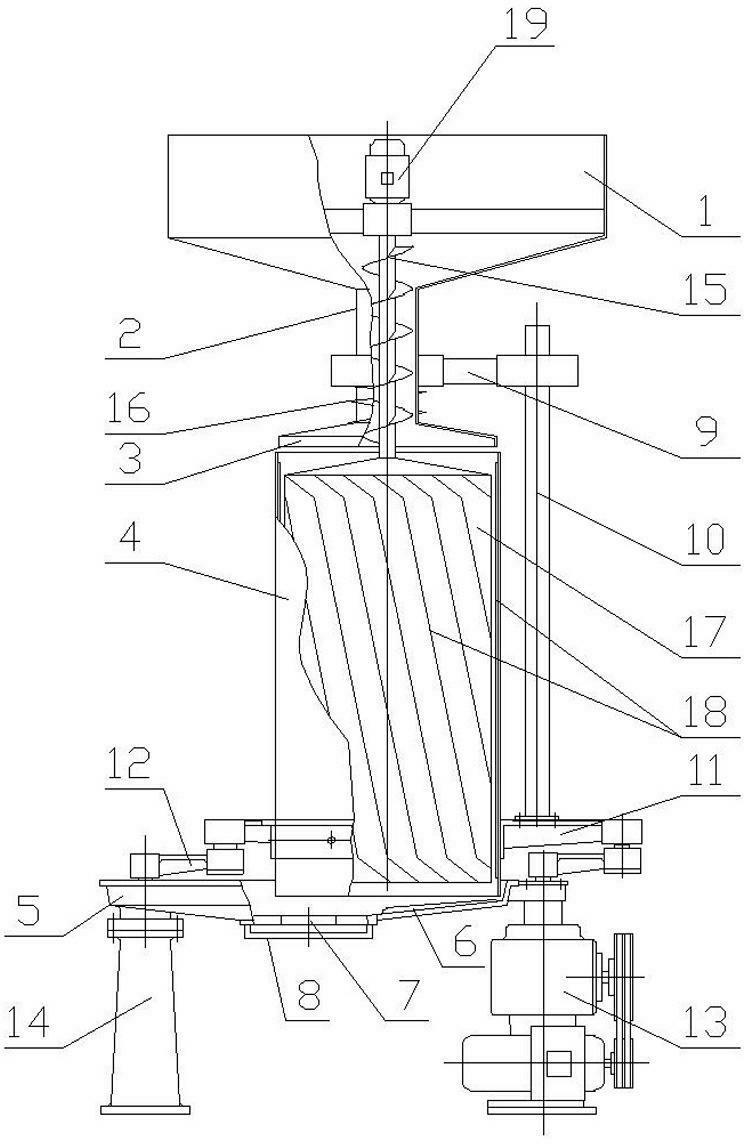
[0019] figure 1 Among them, a tea kneading device for continuously feeding and discharging materials, comprising a frame 14, a power transmission mechanism 13 for controlling the rotation of the kneading barrel 4, a kneading disc 5 arranged below the kneading keg 4, the height of the kneading keg 4 is 1.5 meters, and the kneading disc 5 There is a tea outlet 7 at the bottom, and a tea outlet 8 is provided at the tea outlet 7, and the tea outlet 8 can adjust the size of the tea outlet 7; the kneading barrel 4 is installed on the bracket 11 through three crank rocker mechanisms 12 , wherein a crank rocker mechanism 12 is connected with the power transmission mechanism 13, the power transmission mechanism includes a transmission motor, a transmission box, the transmission motor drives the transmission box to work through a belt, the output end of the transmission box is connected to the crank rocker mechanism 12, and one foot of the bracket 11 The crank rocker mechanism 12 is dri...


PUM

PropertyMeasurementUnit
Heightaaaaaaaaaa

Abstract

The invention relates to a tea leaf rolling device capable of realizing continuous feeding and discharging, which comprises a rack, a power transmission mechanism and a rolling disc. A tea outlet is arranged at the bottom of the rolling disc. A feed hopper is arranged above a rolling barrel. The feed inlet of the feed hopper is connected with a central feed pipe. A gland is arranged between the central feed pipe and the rolling barrel. A rotating shaft with an auger blade is arranged in the center of the feed hopper and the central feed pipe. A rotating roller which is provided with a closed upper end and a closed lower end and is coaxial with the rolling barrel is arranged at the lower end of the rotating shaft. Inclined rolling ribs are respectively distributed on the inner wall of the rolling barrel and the outer wall of the rotating roller. The inner wall of the rolling barrel and the outer wall of the rotating roller form a long and narrow primary rolling area. Under the drive of the auger blade of the rotating shaft, a feeding device can realize continuous tea leaf feeding, tea leaves are continuously and primarily rolled in the long and narrow rolling area, then the tea leaves are re-rolled, the machine is not required to be shut down during processing and continuous rolling is realized; and the rolling pressure and the rolling time are comparatively consistent, the tea leaf rolling quality is even, the rolling speed is fast and the promotion of tea leaf quality is facilitated.

Description

technical field [0001] The invention relates to tea processing equipment, in particular to a tea rolling device. Background technique [0002] With the development of tea processing machinery technology, the division of labor of tea processing equipment is becoming more and more clear. In my country's tea processing process, the tea rolling process has always been completed using the traditional disc rolling machine. The most common structure, such as the Chinese utility model patent No. ZL200920305144.2, is a tea kneading machine, including a frame and a kneading barrel arranged on the frame. The kneading barrel is connected to a transmission power mechanism. Kneading plate, above the kneading barrel, there is a pressurizing mechanism that can exert force on the kneading barrel. The comprehensive action of the ribs installed on the kneading plate destroys the tea cells, thus completing the kneading and forming process. However, there are some deficiencies in the structur...

Claims


Application Information

Patent Timeline
IPC IPC(8): A23F3/06
Inventor 祝小雄
Owner ZHEJIANG ZHUFENG MACHINERY
Learn More