Device with middle lead screw and tailstock for numerical control lathe

A technology of CNC lathes and tailstocks, which is applied in the direction of feeding devices, tailstocks/tops, turning equipment, etc. It can solve the problems of cumbersome installation and debugging of machine tools, large overall quality of CNC machine tools, and inability to carry tailstocks, etc., to achieve loading and unloading Easy, small driving torque, and low manufacturing cost

Active Publication Date: 2013-06-19
CHONGQING HONGGANG CNC MACHINE TOOL
View PDF6 Cites 0 Cited by
  • Summary
  • Abstract
  • Description
  • Claims
  • Application Information

AI Technical Summary

Problems solved by technology

Although this structure has good rigidity and stability of the machine tool, which improves production efficiency and machining accuracy to a certain extent; but its high manufacturing cost makes the use cost high when machining long-axis workpieces, and the overall quality of the CNC machine tool adopting this structure Large, inconvenient to transport, cumbersome to install and debug the machine tool during use
[0005] In the CNC lathes currently on the market, the ball screw used to drive the movement of the large carriage cannot be equipped with a tailstock when it is between the two guide rails. The reason is that there is mechanical interference between the center screw and the tailstock pressure plate.

Method used


Image

  • Device with middle lead screw and tailstock for numerical control lathe
  • Device with middle lead screw and tailstock for numerical control lathe
  • Device with middle lead screw and tailstock for numerical control lathe

Examples


Embodiment Construction

[0017] Below in conjunction with accompanying drawing and embodiment the present invention will be further described:

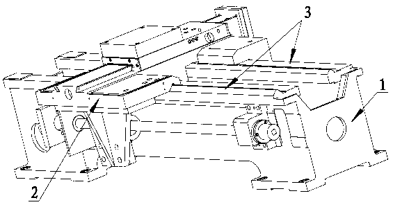
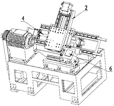
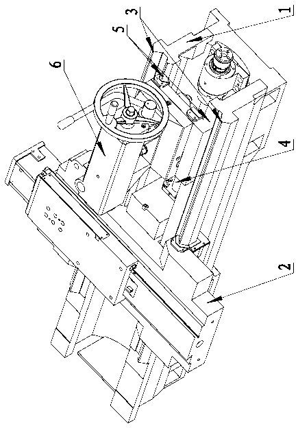
[0018] See attached image 3 , the structure shown in the figure is the first embodiment of the screw rod with tailstock device in the middle of the CNC lathe, including two guide rails 3 integrated with the bed 1, the large carriage 2 installed on the guide rail 3, and the large carriage 2 is connected to the screw rod 4 that controls the movement of the large carriage 2 on the guide rail 3; wherein: the screw rod 4 is arranged between the two guide rails 3, and a tailstock guide rail is arranged on the bed 1 next to the two guide rails 3 5. A tailstock 6 that moves along the tailstock guide rail 5 is provided on the tailstock guide rail 5 , and the tailstock 6 is located directly above the screw rod 4 . The threaded mandrel 4 is arranged in the mounting groove after the bed 1 sinks. This structure is based on the existing structure of the bed, the screw r...


PUM


Abstract

The invention relates to a part for a numerical control lathe, in particular to a device with a middle lead screw and a tailstock for a numerical control lathe. The device comprises two guide rails, a large carriage and the lead screw, wherein the two guide rails are integrated with the lathe body, the large carriage is mounted on the guide rails and connected with the lead screw for controlling the large carriage to move on the guide rails, and the lead screw is arranged between the two guide rails. Tailstock guide rails are arranged on the lathe body beside the two guide rails, the tailstock moving along with the tailstock guide rails is arranged on the tailstock guide rails, and the tailstock is positioned right above the lead screw. Owing to the structure, the device has the advantages of compact structure, low manufacturing cost, high stability in application to the numerical control lathe, high workpiece machining precision and improvement of production efficiency.

Description

technical field [0001] The invention relates to parts for a numerically controlled lathe, in particular to a central screw with a tailstock device for a numerically controlled lathe, which has a simple and compact structure, which enables the machine tool to be more stable, has high machining precision and improves production efficiency. Background technique [0002] In order to achieve better machining of long workpieces, the tailstock and screw rod settings of existing CNC machine tools are roughly divided into the following two forms: [0003] (1), see attached figure 1 , that is, the ordinary flat bed layout form, the flat bed layout form is that the screw rod is set on the side of the bed (1) to drive the movement of the large carriage (2) on the guide rail (3). When this structure uses the tailstock to tighten the workpiece to process any length workpiece, the tailstock will not interfere with the left and right movement of the large carriage and the ball screw driven...

Claims


Application Information

Patent Timeline
Patent Type & Authority Patents(China)
IPC IPC(8): B23Q1/01B23Q5/40B23B3/06B23B17/00B23B23/00
Inventor 汪传宏
Owner CHONGQING HONGGANG CNC MACHINE TOOL
Why Eureka
Try Eureka