
Rapid automatic control die plate locking system especially used for carton printing die cutting machine

A die-cutting machine, fast technology, applied in printing machines, rotary printing machines, printing, etc., can solve the problems of low degree of automation and inconvenient operation, and achieve the effect of saving the number of workers, improving efficiency, and reducing labor costs

Active Publication Date: 2012-07-18
GUANGDONG DONGFANG PRECISION SCI & TECH CO LTD
View PDF5 Cites 7 Cited by
  • Summary
  • Abstract
  • Description
  • Claims
  • Application Information

AI Technical Summary

Problems solved by technology

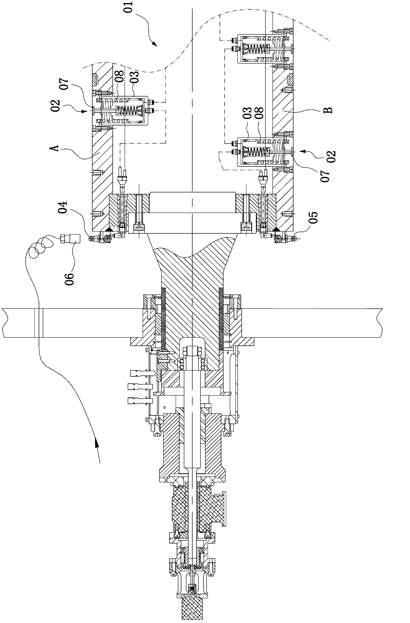
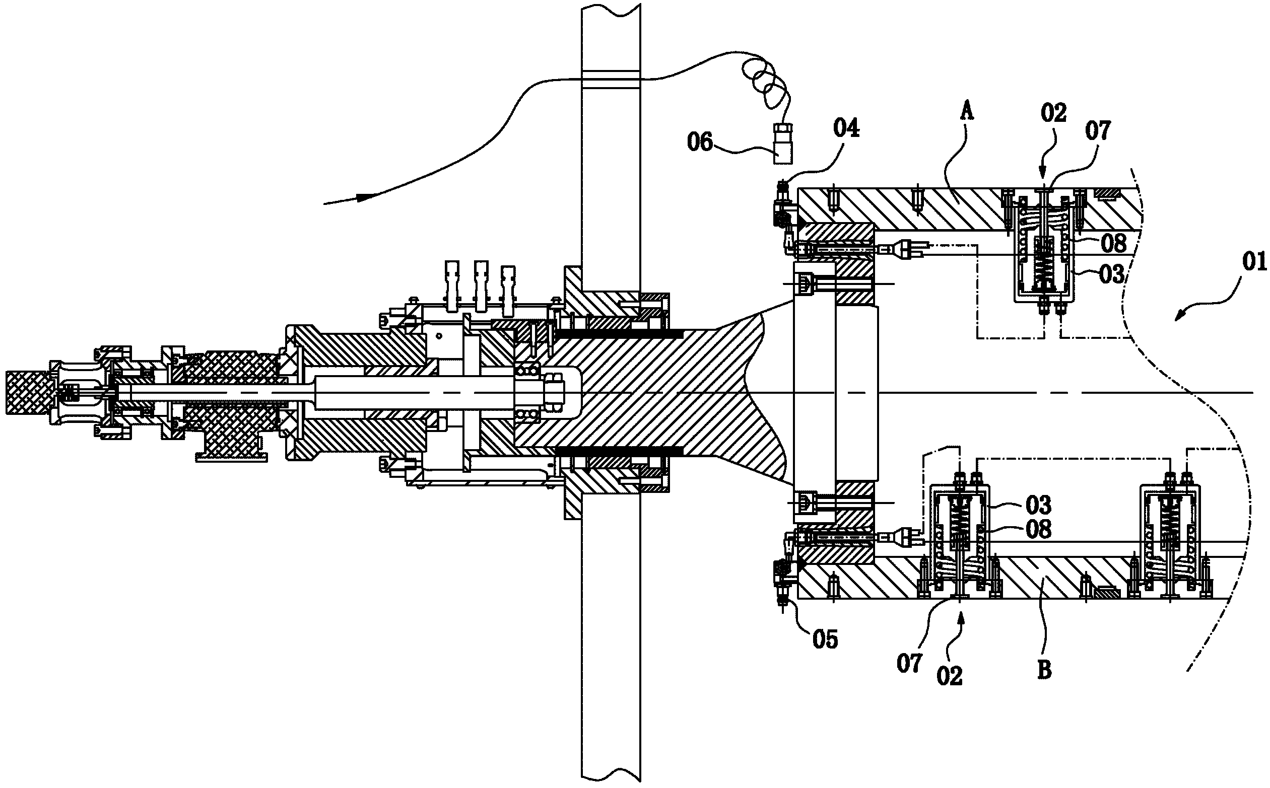
The return spring 08 of the stencil unit 02 drives the mushroom head 07 to retract and fasten the stencil, and the operation needs to be repeated once each piece is installed. This is because the stencil roller is rotating, and the stencil unit 02 inside needs two air paths, so it can only be The quick plug 06 of the gas source is hung on the wallboard, and it can only be plugged in manually when it is used, so it brings inconvenience to the operation and the degree of automation is not high

Method used


Image

  • Rapid automatic control die plate locking system especially used for carton printing die cutting machine
  • Rapid automatic control die plate locking system especially used for carton printing die cutting machine
  • Rapid automatic control die plate locking system especially used for carton printing die cutting machine

Examples


Embodiment Construction

[0010] Below in conjunction with accompanying drawing, the utility patent is further described.

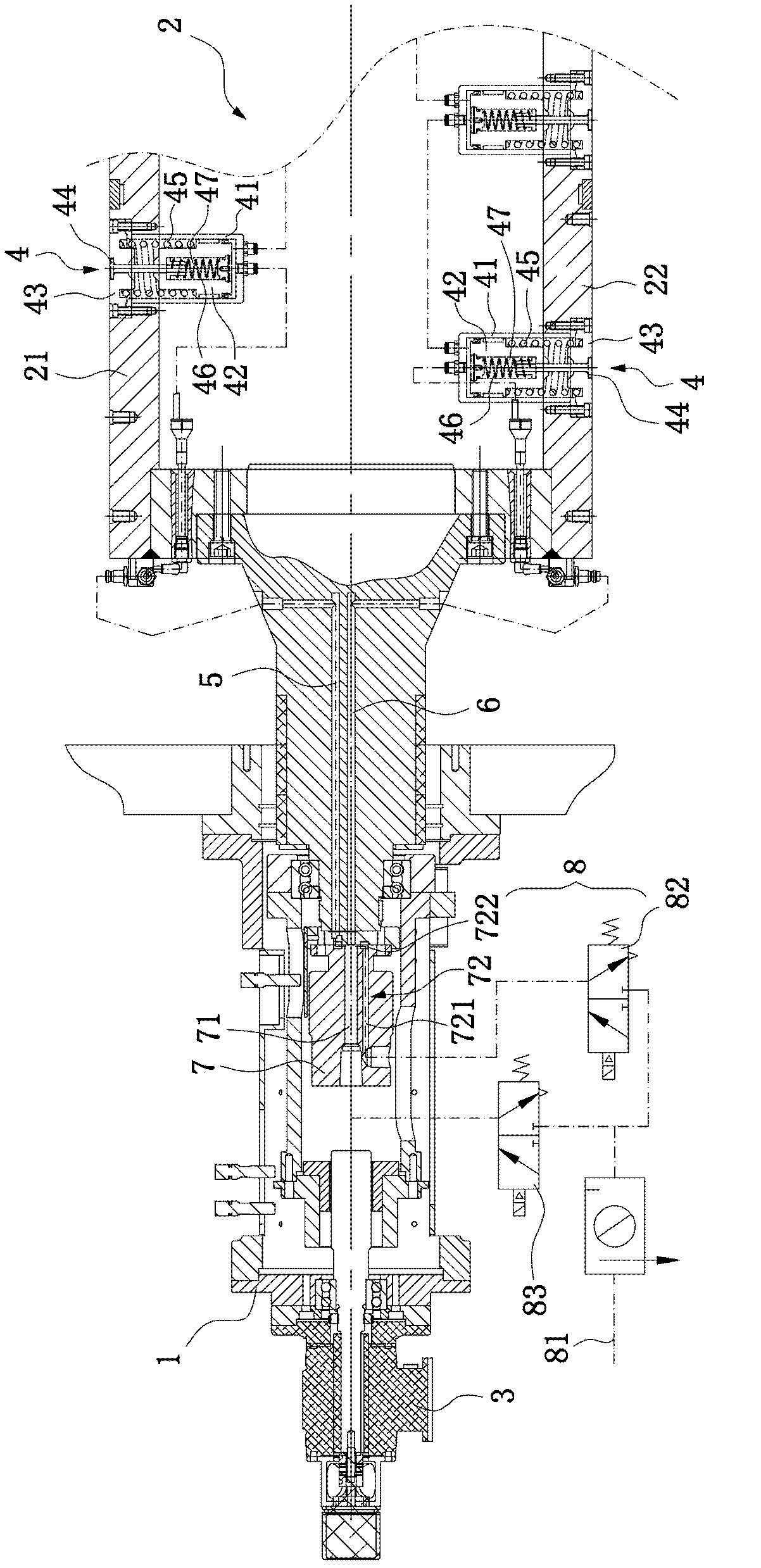
[0011] The die-cutting machine-specific rapid automatic control template locking system of this embodiment includes a wallboard (machine base 1), a template roller body 2, and a device 3 for axially moving the template roller body 2, and two parts of the template roller body 2 The end is installed on the wallboard (base 1) through bearings. The stencil roller body 2 is divided into a first semicircle area 21 and a second semicircle area 22. Each semicircle area is provided with a plurality of pistons for fastening the panel. The inlay unit 4 is provided with two channels at the end of the left shaft head of the stencil roller body 2, the first channel 6 communicates with the bottom of the piston cylinders of all the piston-type inlay units on the first semicircular area 22 of the stencil roller body, The second channel 5 communicates with the piston cylinders of all the piston-typ...


PUM


Abstract

The invention discloses a rapid automatic control die plate locking system especially used for die cutting. The system comprises a wallboard, a die plate roller body and a device for driving the die plate roller body to move horizontally in the axial direction, two ends of the die plate roller body are installed on the wallboard through a bearing, the die plate roller body is divided into a first semicircular region and a second semicircular region, each semicircular region is provided with a plurality of piston type gib units for fastening a panel, two passages are arranged at the end of a left shaft head of the die plate roller body, the first passage is communicated with bottoms of piston cylinders of all the piston type gib units in the first semicircular region of the die plate roller body, the second passage is communicated with piston cylinders of all the piston type gib units in the second semicircular region of the die plate roller body, a gas swivel joint with two passages is arranged at the end of the die plate roller body and is in mutual rotary fit with the die plate roller body, one ends of the two passages of the gas swivel joint are connected with external gas supply equipment, and the other ends of the two passages of the gas swivel joint are respectively connected with the first passage and the second passage of the end of the left shaft head of the die plate roller body.

Description

Technical field: [0001] The invention relates to a special fast automatic control template locking system for a die-cutting machine. Background technique: [0002] At present, in order to install the die-cutting stencil on the stencil roller body of the carton printing die-cutting machine, the die-cutting stencil is generally divided into two semicircular structures. When installing, the two semicircular stencils cover the stencil roller body, and in order to install the stencil, a locking system for locking the stencil is provided on the stencil roller body. The structure of the locking system for locking the stencil on the stencil roller body of the prior art die-cutting machine is: the stencil roller body 01 is divided into two semicircle areas A and B corresponding to the two semicircle templates, each semicircle area is provided with a plurality of piston-type insert units 02, and each semicircle area is respectively equipped with all The joints 04 and 05 at the bottom...

Claims


Application Information

Patent Timeline
IPC IPC(8): B41F19/00
Inventor 唐灼林周文峰
Owner GUANGDONG DONGFANG PRECISION SCI & TECH CO LTD
Learn More