Storage bottle cover and packaging bottle

A bottle cap and material storage technology, which is applied in the field of material storage bottle caps and packaging bottles, can solve problems such as unreasonable packaging structure, inconvenient use, etc., which cannot meet the market and people's health requirements, and achieve freshness preservation effect, long shelf life, The effect of reducing the use of preservatives

Inactive Publication Date: 2012-07-18
何国锋
View PDF5 Cites 3 Cited by
  • Summary
  • Abstract
  • Description
  • Claims
  • Application Information

AI Technical Summary

Problems solved by technology

However, the current existing beverage bottle packaging structure is unreasonable and inconvenient to use, so it cannot meet the health requirements of the market and the people.

Method used


Image

  • Storage bottle cover and packaging bottle
  • Storage bottle cover and packaging bottle
  • Storage bottle cover and packaging bottle

Examples


Embodiment 1

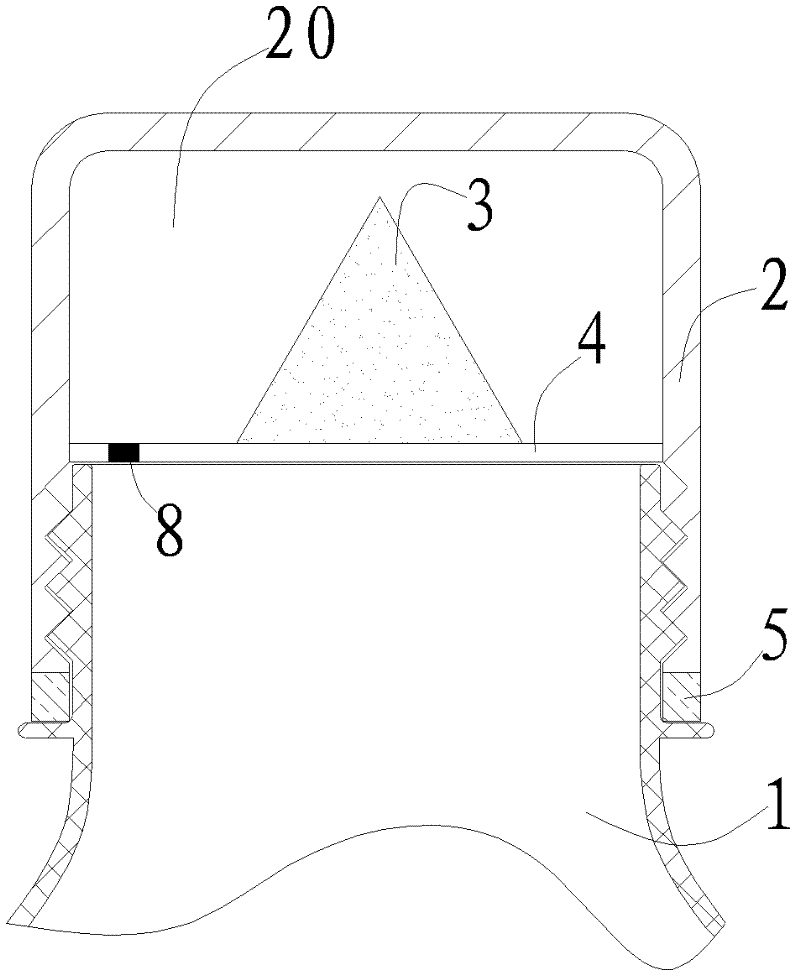
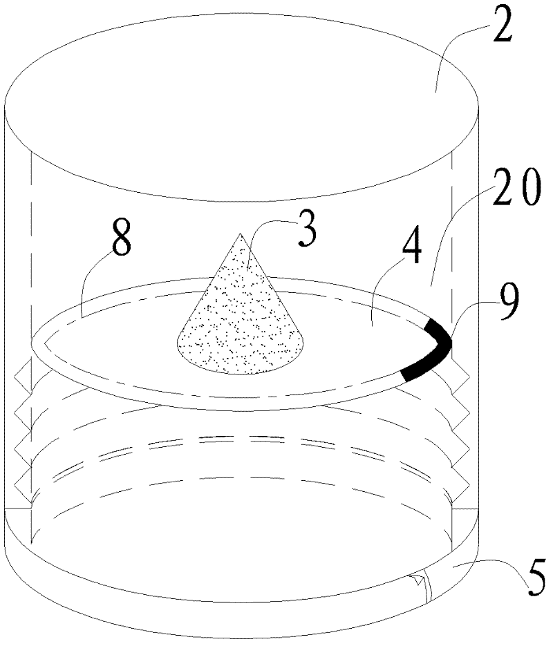
[0023] storage bottle caps, such as figure 1 and figure 2 As shown, a bottle cap body 2 is included, and a diaphragm 4 is arranged inside the bottle cap body 2 to form a sealed material storage space 20 . The storage space 20 is used to store the active ingredient 3 of the beverage concentrate or solid powder. Only when it is used, the diaphragm is pierced to release the active ingredient in the storage space, which can prolong the shelf life and reduce the use of preservatives. To be safer, a weakening line 8 may be provided on the diaphragm 4 to make it easier to release the active ingredient. The diaphragm 4 can be pasted on the inner wall of the bottle cap body 2 . When in use, the bottle cap body 2 can be turned to a certain degree in a tight direction, so that the mouth of the bottle breaks the diaphragm 4, and the active ingredients in the storage space 20 are released. The lower end of the bottle cap body 2 is provided with a safety ring 5 . The active ingredient ...

Embodiment 2

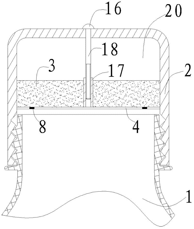
[0025] Such as image 3 and Figure 4 As shown, the diaphragm 4 is fixed on one end of a central axis sleeve 17, the other end of the central axis sleeve 17 is provided with a threaded hole, and one end of a screw 16 is placed in the threaded hole and connected with the central axis sleeve 17 is threaded, and the other end stretches out from the top of the bottle cap body 2, and is threadedly connected with the bottle cap body 2. One end of the screw rod 16 exposed on the top of the bottle cap body is provided with an opening device such as a cross groove or a slot. By rotating the screw 16, the membrane 4 is pulled upwards to tear the membrane, thereby releasing the active ingredient 3 in the material storage space 20 .

Embodiment 3

[0027] Such as Figure 5 As shown, the bottle cap body 2 is provided with a pull-out mouth 6, and a connecting rod 11 is arranged in the pull-out mouth 6 to connect with the diaphragm 4, and the pull-out mouth 6 is pulled upward or rotated to tear the pull-out mouth 6. Cleave the membrane 4 to release the active ingredient 2. Two limiting grooves 13 are arranged inside the bottle cap body 2 . The mouthpiece 6 is placed in the bottle cap body 2, the bottom of which is an elastic limit ring 12, and the limit ring 12 can be stuck in the limit groove 13 in the bottle cap body 2 to prevent the mouthpiece 6 from breaking away from the bottle. Cover 2. When in use, the mouthpiece 6 is pulled out, the connecting rod 11 tears the diaphragm 4, and the active ingredient 3 enters the bottle from the rupture. In addition, this solution can open the mouth 10 on the mouthpiece 6 and avoid the problem of unscrewing the bottle cap to drink.


PUM


Abstract

The invention discloses a storage bottle cover, which comprises a bottle cover body. A storage space sealed by a diaphragm is arranged in the bottle cover body, weakening lines can be arranged on the diaphragm, and the diaphragm can be pasted onto the inner side wall of the bottle cover body. The storage bottle cover has the advantages that effective components and diluted drinking water are separately stored, quality guarantee period is longer, consumption of preservatives can be effectively reduced, a fresh-keeping effect is ensured, and the storage bottle cover is more healthful, safer and convenient in use. The storage bottle cover can be used for the industry of medicines and health care products besides the beverage industry.

Description

【Technical field】 [0001] The invention relates to a packaging bottle structure, in particular to a storage bottle cap and a packaging bottle. 【Background technique】 [0002] Currently popular bottled beverages in the market, although there are many varieties, are all prepared solutions. In order to ensure the stability of the beverage solution, so as not to deteriorate soon, a large amount of stabilizers or preservatives have to be added therein, which not only affects the taste of the beverage, but also seriously endangers the health of drinkers. Following the plasticizer incident in Taiwan in 2011, consumers have higher and higher health requirements for bottled beverages. However, the current existing beverage bottle packaging structure is unreasonable and inconvenient to use, so it cannot meet the health requirements of the market and the people. 【Content of invention】 [0003] The purpose of the present invention is to overcome the shortcomings of the existing bever...

Claims


Application Information

Patent Timeline
Patent Type & Authority Applications(China)
IPC IPC(8): B65D51/28B65D81/32B65D85/72
Inventor 何国锋
Owner 何国锋
Why Eureka
Try Eureka