Continuous reduction annealing furnace for sheet metal strips

A technology of annealing furnace and furnace body, which is applied in the direction of furnace, heat treatment furnace, furnace type, etc. It can solve the problems of unsuitable reduction and descaling of hot-rolled products, large equipment investment, and high production cost, and achieves small footprint and improved surface area. The effect of high quality and production efficiency

Inactive Publication Date: 2012-07-18
UNIV OF SCI & TECH LIAONING
View PDF4 Cites 1 Cited by
  • Summary
  • Abstract
  • Description
  • Claims
  • Application Information

AI Technical Summary

Problems solved by technology

There are many disadvantages in removing the scale by pickling, not only the equipment investment is large, the production cost is high, but also the environment is polluted. Using a reducing gas to reduce this layer of scale to metal (that is, reduction and descaling) can reduce or even eliminate pollution, and at the same time reduce Production cost, increase metal yield
However, reduction and descaling must be carried out with corresponding equipment. However, the existing annealing furnaces are only suitable for heat treatment of cold-rolled products, not suitable for reduction and descaling of hot-rolled products, especially the existing annealing furnaces also have certain shortcomings.

Method used


Image

  • Continuous reduction annealing furnace for sheet metal strips
  • Continuous reduction annealing furnace for sheet metal strips
  • Continuous reduction annealing furnace for sheet metal strips

Examples


Embodiment Construction

[0022] The present invention is specifically described below with an embodiment, which is only an application example of the present invention, and should not be construed as limiting the protection scope of the claims of the present invention.

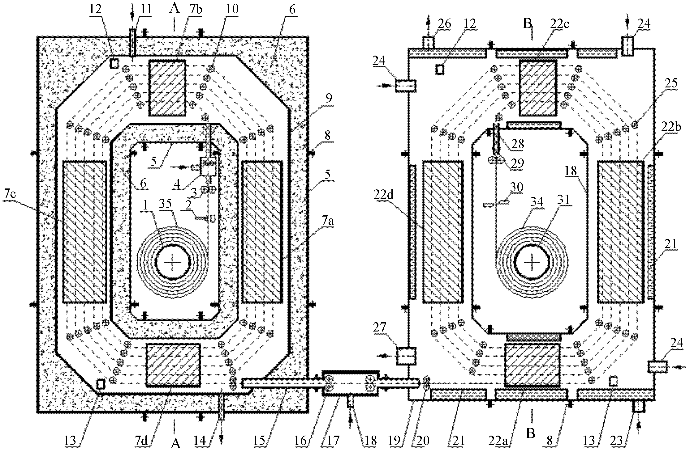
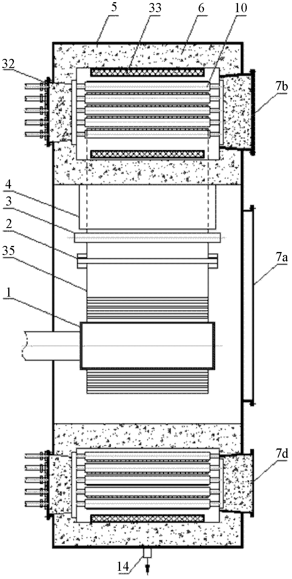
[0023] like figure 1 , figure 2 , image 3 , Figure 4 As shown, the continuous reduction annealing furnace is composed of a furnace body in the heating reduction section, a channel in the middle transition section, and a furnace body in the cooling section. , outer furnace shell 5, insulation layer 6, furnace doors 7a, 7b, 7c, 7d in the heating and reducing section, connecting bolts 8, inner furnace shell 9, guide roller table 10 in the heating and reducing section, reducing gas inlet 11, temperature measuring instrument 12, It consists of a pressure measuring instrument 13, a reducing gas outlet 14, an explosion-proof cover plate 32, and a heater 33;

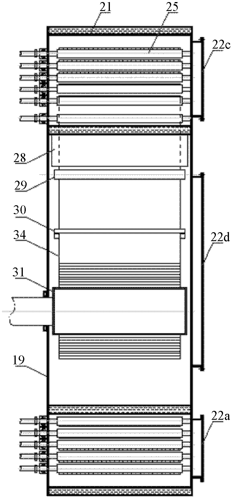
[0024] The channel in the intermediate transition section is composed of a s...


PUM

PropertyMeasurementUnit
thicknessaaaaaaaaaa
widthaaaaaaaaaa
heightaaaaaaaaaa

Abstract

The invention discloses a reduction annealing furnace for continuous reduction and heat treatment of sheet metal strips. By utilizing the reduction annealing furnace, reduction descaling of hot-rolled strips or annealing treatment of cold-rolled strips can be continuously performed in a high-efficient, low-cost and high-quality manner. The reduction annealing furnace comprises a heating reductionsection furnace body, an intermediate transition section channel and a cooling section furnace body, wherein the heating reduction section furnace body comprises an inner furnace shell, an outer furnace shell and an intermediate heat insulation layer, a furnace chamber which is of a hollow square-shaped structure is formed by the furnace shells and the intermediate heat insulation layer, the strips are introduced into the furnace chamber after being opened by an uncoiler at the center of the furnace body, revolved for a plurality of circles through the guide of a guide roller table in the furnace chamber, then heated, reduced or annealed and then led out of the furnace body, and further enter into the cooling section furnace body via the intermediate transition channel, the cooling section furnace body is of a hollow square-shaped cooling chamber constituted by the multiple sections of housings, and the strips are revolved for the plurality of the circles in the cooling chamber, cooled in a non-oxidation manner and coiled into strip coils by a coiling machine. The reduction annealing furnace disclosed by the invention has the advantages of low equipment investment, small floor area, low production cost and good product quality.

Description

technical field [0001] The invention relates to a metal material heat treatment device, in particular to a metal strip continuous reduction annealing furnace. Background technique [0002] Metal materials generally produce work hardening after cold working deformation. After work hardening, the strength and hardness of the material increase, and the plastic toughness decreases, which makes further processing and application difficult. In order to eliminate this work hardening phenomenon, annealing is generally required. At this time, an annealing furnace is generally used for annealing treatment. For example, bell-type annealing furnaces or continuous annealing furnaces are generally used for annealing after strip steel is cold-rolled, and continuous annealing furnaces are divided into two types: horizontal and tower. At present, these types of annealing furnaces have their own advantages and disadvantages. Although the bell-type annealing furnace has a simple structure and...

Claims


Application Information

Patent Timeline
Patent Type & Authority Applications(China)
IPC IPC(8): C21D9/56
Inventor 井玉安胡希达朱开元
Owner UNIV OF SCI & TECH LIAONING
Why Eureka
Try Eureka