
Steel tube-I beam combination steel tube concrete special-shaped columns and manufacture method thereof

A technology of combining steel pipes and I-beams, applied in the directions of columns, piers, pillars, etc., can solve the problems of reducing the bearing capacity of components, poor shear and torsional bearing capacity, and easy premature buckling, so as to improve the bearing capacity and Seismic capacity, improved bearing capacity and ductility, effect of preventing premature buckling

Inactive Publication Date: 2012-07-18
TIANJIN UNIV
View PDF3 Cites 54 Cited by
  • Summary
  • Abstract
  • Description
  • Claims
  • Application Information

AI Technical Summary

Problems solved by technology

[0003] In the architectural design, in order to meet the architectural requirements and avoid the impact of the protruding edges and corners of the corner columns on the view and occupied space of the house, and to improve the flexibility of the furniture arrangement in the house, the reinforced concrete special-shaped column structure with the same thickness as the column wall and the filling wall has been widely used, but the concrete It is easy to crack, so the shear and torsional bearing capacity of the column is poor, so the seismic capacity is insufficient
At present, some scholars have proposed a variety of cross-sectional forms of CFST special-shaped columns, but when the width-thickness ratio is large, the steel tubes have a weak ability to restrain the concrete, which is prone to premature buckling and reduces the bearing capacity of the components.
[0004] In order to solve the poor seismic capacity of reinforced concrete special-shaped columns and the shortcomings of steel pipe concrete columns, it is necessary to find a special-shaped column with good ductility and high bearing capacity

Method used


Image

  • Steel tube-I beam combination steel tube concrete special-shaped columns and manufacture method thereof
  • Steel tube-I beam combination steel tube concrete special-shaped columns and manufacture method thereof
  • Steel tube-I beam combination steel tube concrete special-shaped columns and manufacture method thereof

Examples


Embodiment Construction

[0032] The present invention will be described in further detail below in conjunction with the accompanying drawings.

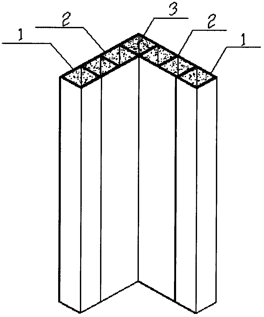
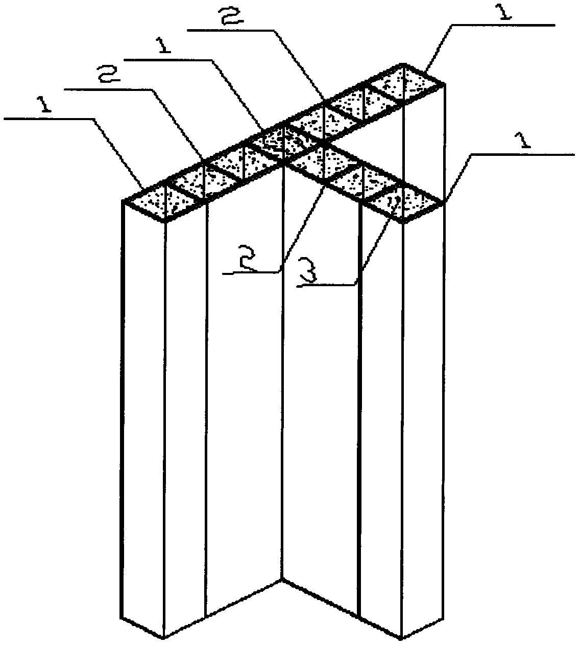
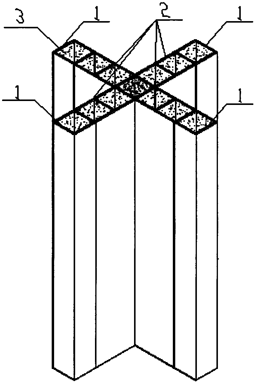
[0033] Such as Figure 1-10 As shown, the present invention provides a steel pipe-I-steel combined steel pipe concrete special-shaped column, which consists of a steel pipe 1, an I-steel 2, and concrete 3 poured therein. The column is to weld the I-beam on the adjacent side of the steel pipe, and then weld the steel pipe 1 to the other end of the I-beam 2, and connect multiple steel pipes 1 and I-beam 2 to form a cross-sectional shape of L-shape, T-shape or ten. Shaped steel pipe-I-steel composite steel pipe concrete special-shaped column, and then fill the space separated by steel pipe and I-steel with concrete. Steel pipe 1 is welded or rolled; working steel 2 is welded or rolled, such as figure 1 and figure 2 shown.

[0034] The steel pipe-I-steel composite steel pipe concrete special-shaped column refers to that the components are transported to the ...


PUM


Abstract

The invention relates to steel tube-I-beam combination steel tube concrete special-shaped columns, which comprises steel tubes, I-beams and concrete poured inside the special-shaped columns. The steel tubes and the I-beams are welded together to compose the special-shaped columns with different sections. The whole sections are separated through the steel tubes and the I-beams, then the concrete is filled in separation spaces of the steel tubes and the I-beams, the steel tubes can be made by welding or rolling, and the I-beams can be made by welding or rolling. The steel tube-I-beam combination steel tube concrete special-shaped columns have the advantages that inside corner steel tube walls and I-beam flange steel plates are communicated with each other so as to overcome the defect that force delivery of inside corner portions of other steel tube concrete special-shaped columns is unclear, and whole working capacity of steel tube concrete special-shaped columns is improved. The steel tubes are placed at the edges and at corner portions of the sections so as to improve restrain capacity of the special-shaped columns. The steel tubes and the I-beams separate the concrete of the special-shaped columns, width-to-thickness ratio of the steel plates is reduced, bearing capacity and shock-resistance are improved, production and assembly of the special-shaped columns are modularized, and simultaneously construction speed is fast.

Description

technical field [0001] The invention specifically relates to a steel pipe-I-steel combined steel pipe concrete special-shaped column and a manufacturing method thereof. Background technique [0002] Concrete filled steel pipe is a structural member formed by filling concrete in steel pipes, and the steel pipes and their core concrete can jointly bear external loads. The supporting function of the filled concrete can prevent premature buckling of the steel tube wall, and at the same time, the steel tube can restrain the core concrete, so that the steel tube concrete has a high bearing capacity; at the same time, the steel tube concrete has good plasticity and toughness, and has good earthquake resistance. Strong and other advantages. Therefore, CFST has broad application prospects. [0003] In the architectural design, in order to meet the architectural requirements and avoid the impact of the protruding edges and corners of the corner columns on the view and occupied space...

Claims


Application Information

Patent Timeline
IPC IPC(8): E04C3/34E04G21/00
Inventor 陈志华郑亮
Owner TIANJIN UNIV
Learn More