Reciprocating rolling generator and application method thereof

A generator and reciprocating technology, applied in the direction of machines/engines, mechanical equipment, mechanisms for generating mechanical power, etc., can solve the problems of low energy conversion rate and poor continuity of energy conversion, so as to improve power generation efficiency, increase service life, The effect of increasing the service life

Inactive Publication Date: 2012-07-18
SICHUAN KODER ENERGY SAVING & ENVIRONMENTAL PROTECTION TECH
View PDF9 Cites 7 Cited by
  • Summary
  • Abstract
  • Description
  • Claims
  • Application Information

AI Technical Summary

Problems solved by technology

[0004] The purpose of the present invention is to provide a reciprocating rolling generator to solve the problem of low energy conversion rate caused by the poor continuity of energy conversion in current rolling power generation devices

Method used


Image

  • Reciprocating rolling generator and application method thereof
  • Reciprocating rolling generator and application method thereof
  • Reciprocating rolling generator and application method thereof

Examples


Embodiment 1

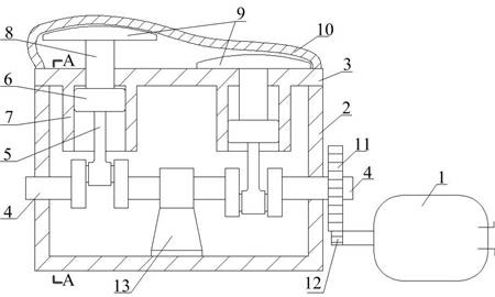
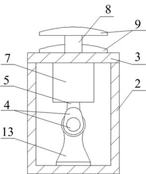
[0037] Such as figure 1 with image 3 As shown, the reciprocating rolling generator includes a generator 1 and an energy transfer device connected to the generator; the energy transfer device includes a box body composed of a box-shaped base 2 and a box cover 3, which is connected to the generator 1 The crankshaft 4 is placed in the box and penetrates both sides thereof, and a transmission device that passes through the cover 3 and is connected to the crankshaft 4; the transmission is mainly composed of a slide 7 connected to the lower part of the cover 3 and a slide 7 The inner slider 6, the connecting rod 5 connecting the slider 6 and the crankshaft 4, the support rod 8 passing through the box cover 3 and connected with the slider 6, and the pressure plate 9 arranged above the box cover 3 and connected with the support rod 8 There are two sets of transmission devices. In order to ensure the more efficient operation of the present invention, correspondingly, the connecting rod...

Embodiment 2

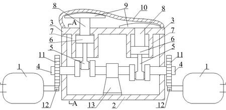
[0049] Such as figure 2 with 3 As shown, the difference between this embodiment and Embodiment 1 is that both ends of the crankshaft 4 are provided with driving gears 11, and two generators 1 are connected by meshing with corresponding driven gears 12. Such a setting can drive the two generators 1 to generate electricity at the same time when the crankshaft 4 rotates, make full use of the energy transmitted by the rotation of the crankshaft 4, increase power output, greatly improve power generation efficiency and reduce resource occupancy.


PUM


Abstract

The invention discloses a reciprocating rolling generator, which belongs to the field of highway energy recovery, and solves the problem of low energy conversion efficiency caused by poor continuity of energy conversion of a current rolling generation device. The reciprocating rolling generator comprises a generator and an energy transfer device connected with the generator. The energy transfer device comprises a box, a crankshaft and two transmission devices, wherein the box is composed of a box base and a box cover, the crankshaft is connected to the generator and disposed inside the box, and the two transmission devices penetrating through the box cover are connected to the crankshaft. Each transmission device mainly comprises a slide way, a slider, a connecting rod, a support rod and a pressing plate, wherein the slide way is connected to the lower portion of the box cover, the slider is disposed inside the slide way, the connecting rod is used for connecting the slider with the crankshaft, the supporting rod penetrating through the box cover is connected with the slider, and the pressing plate arranged above the box cover is connected with the support rod. The reciprocating rolling generator is ingenious in design and low in production cost, a crank-link mechanism reciprocates to drive the generator to continuously apply work so that the energy conversion efficiency is greatly improved, and the reciprocating rolling generator has quite high popularization value.

Description

Technical field [0001] The invention relates to a generator, in particular to a reciprocating roller compaction generator and an application method thereof. Background technique [0002] Energy is an important resource for human survival and development. Economic development and the improvement of people's living standards must first rely on energy development. Existing conventional energy sources include renewable water resources and non-renewable resources such as coal, oil, natural gas, etc.; new energy sources include solar energy, wind energy, geothermal energy, ocean energy, biological energy, hydrogen energy, and nuclear power generation Nuclear fuel and other energy sources; a large amount of ineffective mechanical energy is produced in the process of human work and life. For example, the pressure on the ground when a vehicle is driving can become a condition for generating energy. How to efficiently collect this part of energy and make it a new type of green energy? Has...

Claims


Application Information

Patent Timeline
Patent Type & Authority Applications(China)
IPC IPC(8): F03G7/00
Inventor 李远志
Owner SICHUAN KODER ENERGY SAVING & ENVIRONMENTAL PROTECTION TECH
Why Eureka
Try Eureka