Low-inertia plunger resisting pressure impact

A low-inertia, anti-pressure technology, applied in the field of plungers, can solve the problem that the plunger cannot take into account low inertia and flow pulsation, and achieve the effects of reducing inertial force, reducing noise, and reducing quality

Active Publication Date: 2012-07-18
ZHEJIANG UNIV
View PDF6 Cites 4 Cited by
  • Summary
  • Abstract
  • Description
  • Claims
  • Application Information

AI Technical Summary

Problems solved by technology

[0004] In order to overcome the deficiency that the existing plunger cannot take into account both low inertia and flow pulsation, the present invention provides a low-inertia plunger that can not only reduce the plunger inertia, but also reduce the flow pulsation and resist pressure shock

Method used


Image

  • Low-inertia plunger resisting pressure impact
  • Low-inertia plunger resisting pressure impact
  • Low-inertia plunger resisting pressure impact

Examples


Embodiment Construction

[0018] The present invention will be further described below in conjunction with the accompanying drawings.

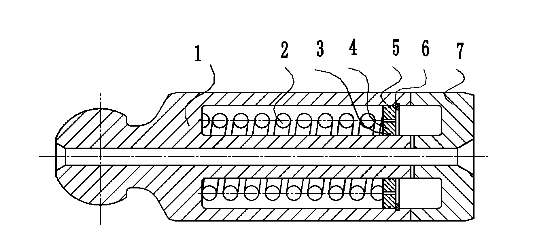
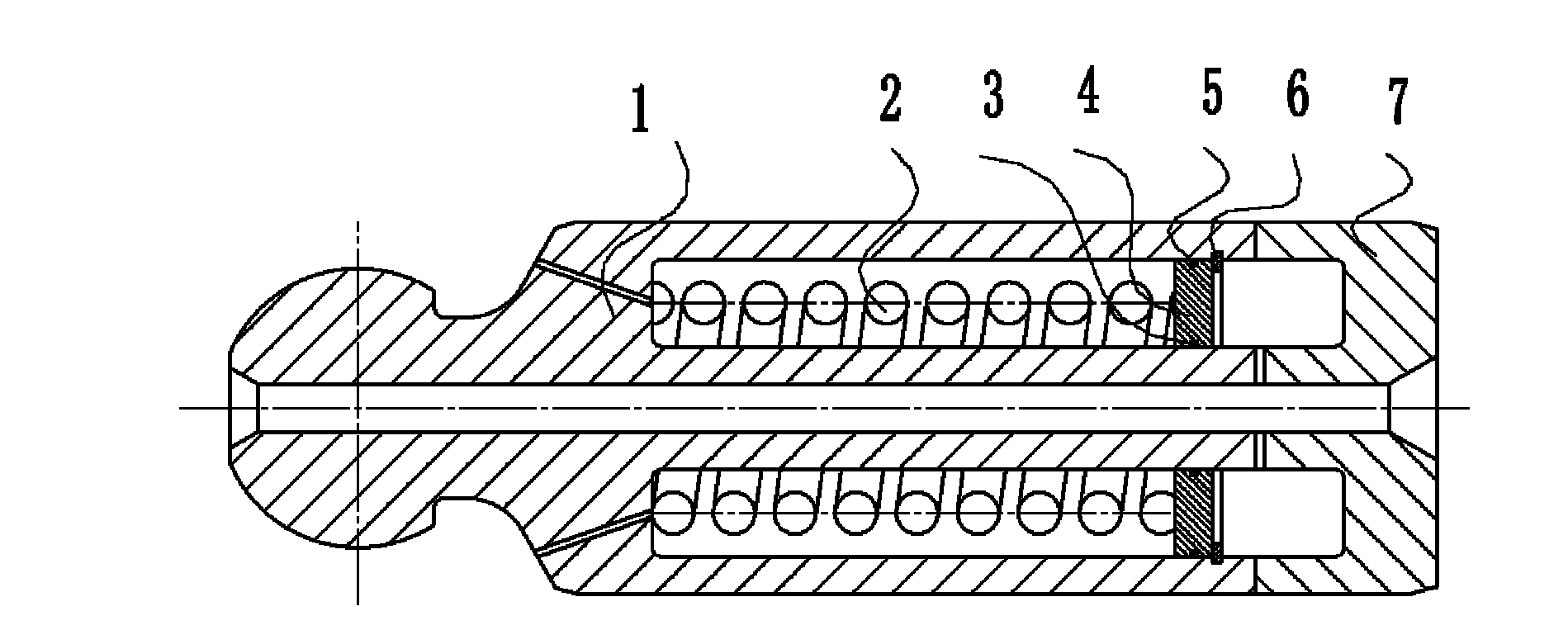
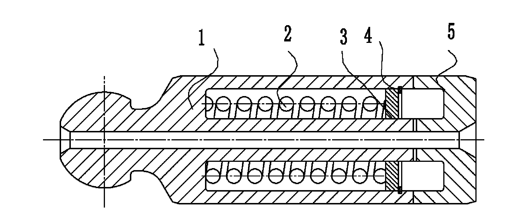
[0019] refer to Figure 1 to Figure 5 , a low-inertia plunger resistant to pressure shock, the low-inertia plunger includes a left plunger body 1 and a right plunger body 7, the right end face of the left plunger body 1 and the left end face of the right plunger body 7 Fixedly connected, the middle part of the left plunger body 1 and the right plunger body 7 is provided with a central cavity; the left plunger body 1 is processed with an axially arranged left annular groove, and the opening of the left annular groove is located at On the right end face of the left plunger body, a spring 2, an annular retaining ring 4, an inner sealing ring 3, an outer sealing ring 5 and a snap ring 6 are installed in the left annular groove, and the rear end of the spring 2 is pushed against the left The bottom of the annular groove, the front end of the spring 2 is on the annular reta...


PUM


Abstract

A low-inertia plunger resisting pressure impact comprises a left plunger body and a right plunger body. The right end face of the left plunger body is fixedly connected with the left end face of the right plunger body, and a center cavity is formed in the middle of the left plunger body and the right plunger body. A left annular groove arranged circumferentially is formed on the left plunger body, the opening of the left annular groove is located on the right end face of the left plunger body, a spring, an annular retainer ring and a snap ring are mounted in the left annular groove, the back end of the spring is butted to the bottom of the left annular groove, the front end of the spring is butted against the annular retainer ring, the annular retainer ring is slidably hermetically mounted in the left annular groove and is limited by the snap ring, and the snap ring is mounted in the left annular groove. A right annular groove is circumferentially formed on the right plunger body, the opening of the right annular groove is located on the left end face of the right plunger body, and is communicated with that of the left annular groove, and the right annular groove is communicated with the center cavity through a through hole. Both the inertia of the plunger and flow pulsation can be reduced.

Description

technical field [0001] The invention relates to a plunger, especially a low-inertia plunger. Background technique [0002] The plunger is an important component in the plunger pump, and its performance affects the quality of the plunger pump. The movement of the plunger is more complicated, including linear movement along the axial direction, rotational movement around the main shaft of the plunger pump, and rotation around its own axis. At the same time, the plunger is the part connecting the liquid and the solid, and it is the link that transmits the force of the hydraulic oil to the swash plate, and the change of the flow rate of the hydraulic oil causes flow pulsation, which causes fluid noise; the change of the force and moment on the swash plate causes Mechanical vibration, causing mechanical noise. With the world's pursuit of energy saving and environmental protection, the high noise level generated on the axial piston pump and the energy consumption on the control ...

Claims


Application Information

Patent Timeline
Patent Type & Authority Applications(China)
IPC IPC(8): F04B53/14
Inventor 徐兵叶绍干张军辉杜睿龙
Owner ZHEJIANG UNIV
Why Eureka
Try Eureka