Ultrasonic subcooling eliminating device

A supercooling removal and ultrasonic technology, which is applied in the manufacture of ice, lighting and heating equipment, ice making, etc., can solve the problems of not being able to remove supercooling well, the efficiency of removing supercooling is not high, and the removal of supercooling is not sufficient. Achieve the effect of improving the effect of supercooling relief, good effect of supercooling relief, and sufficient effect of supercooling relief

Active Publication Date: 2012-07-18
陈国全
View PDF9 Cites 6 Cited by
  • Summary
  • Abstract
  • Description
  • Claims
  • Application Information

AI Technical Summary

Problems solved by technology

However, the existing supercooling device based on the principle of ultrasonic desupercooling can not relieve supercooling well, and...

Method used


Image

  • Ultrasonic subcooling eliminating device
  • Ultrasonic subcooling eliminating device
  • Ultrasonic subcooling eliminating device

Examples


Embodiment 1

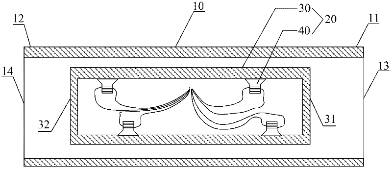
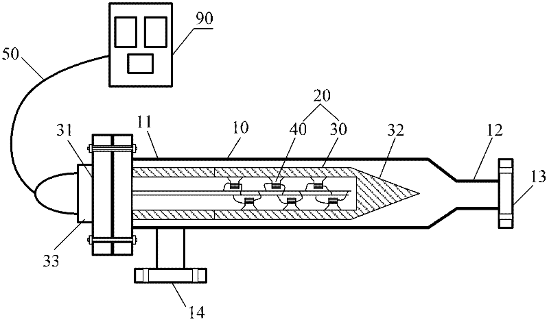
[0039] Embodiment one: like figure 2As shown, the first end 31 of the ultrasonic device casing 30 is fixedly connected to the first end 11 of the outer tube 10 , that is, the ultrasonic device and the outer tube 10 are directly fixedly connected. The first end 31 of the casing 30 is fixed, and the rest of the casing 30 (including the second end) can be directly "suspended" in the outer tube 10, or can be defined by further reinforcement means, for example, between the casing 30 and the outer tube 10. A limiting component or a connecting component is provided between the tubes 10 to limit the relative spatial position between the housing 30 and the outer tube 10 . The first end 31 of the housing 30 and the first end 11 of the outer tube 10 can adopt various existing connection techniques, such as conventional flange connection methods. To improve the sealing effect between the liquid and prevent liquid leakage, a sealing member should also be provided at the flange connecti...

Embodiment 2

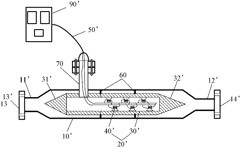
[0044] Embodiment two: like image 3 , Figure 4 As shown, the ultrasonic device 20' of this embodiment is provided with a supporting fixture 60 between the outer wall surface of the casing 30' and the inner wall surface of the outer tube 10'. The supporting and fixing member 60 can adopt an embedded part, that is, the part is not directly fixed with the housing 30' or the outer tube 10', but realizes the gap between the housing 30' and the outer tube 10' through the limiting function of the part. The relative fixation; the supporting fixture 60 can also be a connected component, that is, the component is fixedly connected with the housing 30' and / or the outer tube 10', such as welding, threaded connection and the like. At this time, since the two ends of the outer tube 10' are not blocked, the first outlet 13' and the second outlet 14' of the outer tube 10' can be directly arranged at the two ends 11', 12 of the outer tube 10' respectively. '.

[0045] The outer tube 10'...


PUM


Abstract

The invention relates to subcooled-water ice-making technology, in particular to an ultrasonic subcooling eliminating device. The ultrasonic subcooling eliminating device comprises an external pipe for conveying subcooled liquid and an ultrasonic device for applying ultrasonic to the subcooled liquid in the external pipe, wherein the external pipe is provided with a first outlet and a second outlet and comprises a first end and a second end; and the ultrasonic subcooling eliminating device is characterized in that the ultrasonic device is arranged inside the external pipe and comprises a casing which is fixedly arranged inside the external pipe and is provided with a cavity therein, and a plurality of ultrasound transducers which are arranged inside the casing; and the casing comprises a first end and a second end. Compared with the conventional ultrasonic subcooling eliminating device, the ultrasonic subcooling eliminating device disclosed by the invention has the advantages that the subcooling elimination is more sufficient; the energy consumption is lower; and the subcooling eliminating effect is better.

Description

technical field [0001] The invention relates to supercooled water ice making technology, in particular to an ultrasonic supercooling release device. Background technique [0002] Ice storage technology utilizes the refrigeration main engine to cool during the low-peak period of the power grid, and the cold storage equipment stores the cold energy, and releases the cold energy during the peak hours of the power grid. It is an important technology to achieve peak shifting and energy saving. There are two ice-making methods of ice storage technology, one is the traditional ice hockey and coil ice-making methods, and the other is the dynamic ice-making method gradually developed in the 1990s, that is, the supercooled water ice-making method. Due to the high ice production rate and energy efficiency of supercooled water ice making, more and more people pay attention to it. [0003] The supercooled water ice making system usually includes a supercooling device, a supercooling rel...

Claims


Application Information

Patent Timeline
IPC IPC(8): F25C1/00
Inventor 江卫红
Owner 陈国全
Why Eureka
Try Eureka