Pure-countercurrent cellular plate-pin heat exchanger and combination thereof

A technology of fin heat exchanger and honeycomb plate, applied in the direction of heat exchanger type, indirect heat exchanger, fixed plate duct assembly, etc. Large flow, increase fan output power, etc., to achieve the effect of light weight, compact structure, and improved heat transfer coefficient

Active Publication Date: 2012-07-18
JIANGSU TONGSHENG HEAT EXCHANGER
View PDF3 Cites 32 Cited by
  • Summary
  • Abstract
  • Description
  • Claims
  • Application Information

AI Technical Summary

Problems solved by technology

However, the existing plate-fin heat exchangers and micro-channel heat exchangers also have the following defects: for example, it is difficult for the counter-flow plate-fin heat exchanger to achieve pure counter-flow micro-channel heat exchange, while the micro-channel heat exchanger is difficult Achieve pure countercurrent and large flow heat exchange; plate-fin heat exchangers are equipped with deflectors and heads, so they are large in size and complex in structure, which greatly increase

Method used


Image

  • Pure-countercurrent cellular plate-pin heat exchanger and combination thereof
  • Pure-countercurrent cellular plate-pin heat exchanger and combination thereof
  • Pure-countercurrent cellular plate-pin heat exchanger and combination thereof

Examples


Embodiment 1

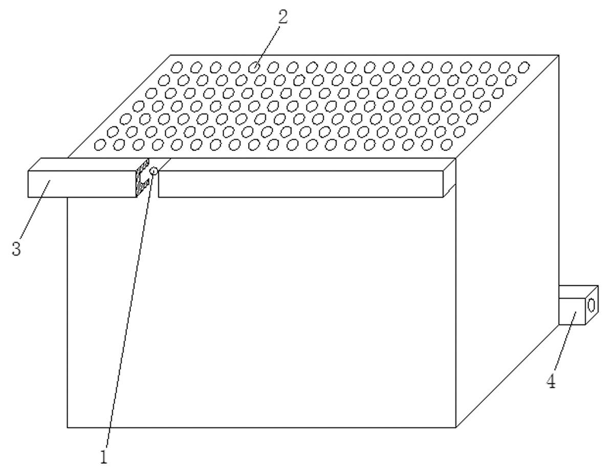
[0022] refer to figure 1 , this embodiment includes a honeycomb heat exchange unit body, the honeycomb heat exchange unit body is provided with a circulation channel A1 and a circulation channel B2 for different fluids, and the circulation channel A1 and the circulation channel B2 are parallel to the surface Alternately arranged, one end of the circulation channel B2 is a fluid inlet, and the other end is a fluid outlet, the circulation channel A1 includes a vertical circulation channel (not shown in the figure) parallel to the circulation channel B2, and one end of the vertical circulation channel The inlet on the upper left side of the heat exchange unit body is connected through a horizontal distribution channel (not shown in the figure), and the other end of the longitudinal flow channel is connected to the right side of the heat exchange unit body through a horizontal confluence channel (not shown in the figure). The outlet at the lower part of the side is connected.

[...

Embodiment 2

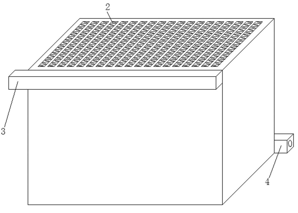
[0028] refer to figure 2 , The difference between this embodiment and Embodiment 1 is: the shape of the honeycomb hole of the circulation channel B2 is triangular. Of course, the shape of the honeycomb holes of the circulation channel B can also be hexagonal, square, rectangular, etc., which will not be repeated here.

Embodiment 3

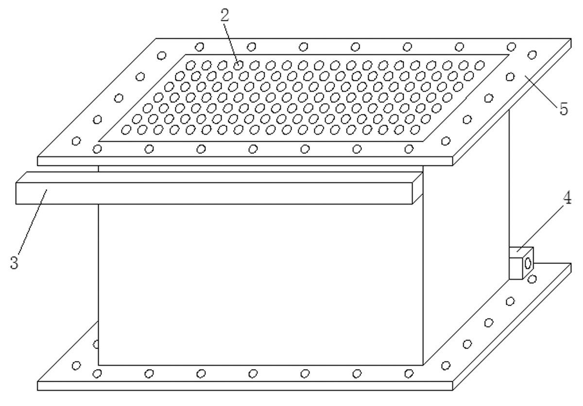
[0030] refer to image 3 , The difference between this embodiment and Embodiment 1 is that: the end faces of the inlets and outlets of the circulation channel B2 are respectively provided with connecting flanges 5 .


PUM


Abstract

The invention discloses a pure-countercurrent cellular plate-pin heat exchanger and a combination thereof. The heat exchanger comprises a cellular heat exchange unit body, a flow channels A and flow channels B which are for different fluids are arranged in the cellular heat exchange unit body and staggered in a way that the planes wherein the flow channels A and flow channels B are located are parallel, one end of each flow channel B is provided with a fluid inlet and the other end of each flow channel B is provided with a fluid outlet, each flow channel A comprises a longitudinal flow channel parallel to the flow channels B, one end of each longitudinal flow channel is connected with an inlet on the upper left of heat exchange unit body through transverse distributive channels, and the other end of each longitudinal flow channel is connected with an outlet on the lower right of heat exchange unit body through transverse converge channels. The invention further provides a combination of the pure-countercurrent cellular plate-pin heat exchanger. The pure-countercurrent cellular plate-pin heat exchanger and the combination thereof are simple in structure, low in production cost, low in resistance, high in processing flow and high in heat exchange efficiency, and uniform distribution can be realized.

Description

technical field [0001] The invention relates to a honeycomb plate-fin heat exchanger and its combination, in particular to a honeycomb plate-fin heat exchanger and its combination capable of realizing modular combination of pure reverse flow. Background technique [0002] Partitioning wall heat exchangers can be divided into shell and tube heat exchangers, plate heat exchangers, casing heat exchangers, etc. according to different heat transfer surfaces, among which plate-fin heat exchangers and microchannel heat exchangers are The two most ideal heat exchangers in today's radiators. However, the existing plate-fin heat exchangers and micro-channel heat exchangers also have the following defects: for example, it is difficult for the counter-flow plate-fin heat exchanger to achieve pure counter-flow micro-channel heat exchange, while the micro-channel heat exchanger is difficult Achieve pure countercurrent and large flow heat exchange; plate-fin heat exchangers are equipped w...

Claims


Application Information

Patent Timeline
IPC IPC(8): F28D9/00
Inventor 刘小江
Owner JIANGSU TONGSHENG HEAT EXCHANGER
Why Eureka
Try Eureka