Resonance peak-based ultrasonic cavitation state identification method

A technology of cavitation state and identification method, which is applied in the direction of using sound wave/ultrasonic wave/infrasonic wave to analyze fluids, etc. It can solve the problems of lack of detection and identification methods of ultrasonic cavitation state and unsatisfactory ultrasonic cavitation

Inactive Publication Date: 2012-07-18
TSINGHUA UNIV
View PDF1 Cites 8 Cited by
  • Summary
  • Abstract
  • Description
  • Claims
  • Application Information

AI Technical Summary

Problems solved by technology

However, the application of ultrasonic cavitation is not satisfactory, one of the main reasons i

Method used


Image

  • Resonance peak-based ultrasonic cavitation state identification method
  • Resonance peak-based ultrasonic cavitation state identification method
  • Resonance peak-based ultrasonic cavitation state identification method

Examples


Embodiment Construction

[0027] The technical solutions of the present invention will be described in detail below with reference to the accompanying drawings and preferred embodiments.

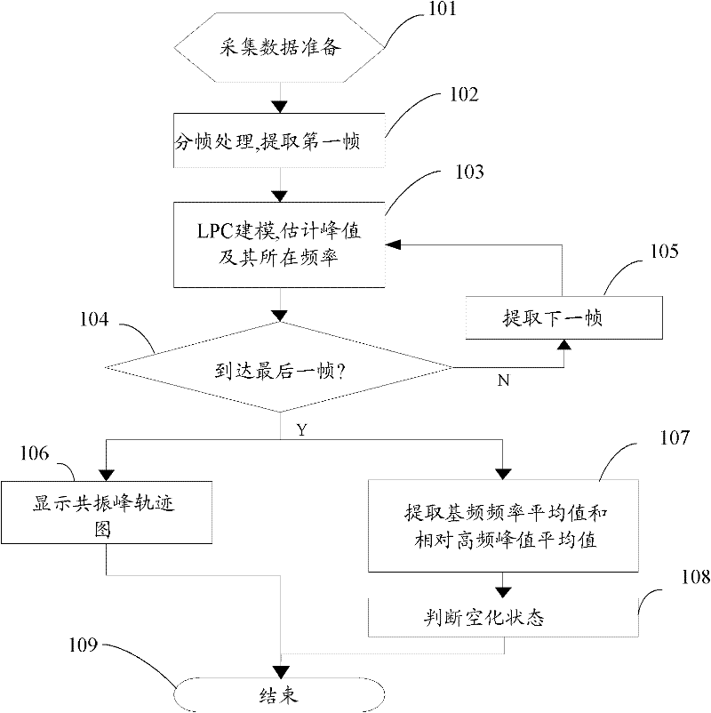
[0028] Such as figure 1 As shown, it is a processing flow chart of a formant-based ultrasonic cavitation state identification method of the present invention. A method for identifying ultrasonic cavitation states based on resonance peaks of the present invention comprises the following specific steps:

[0029] Step 101: collecting signal data of an ultrasonic cavitation field within a set time period.

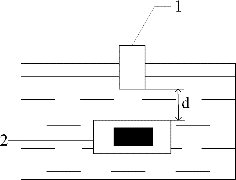
[0030] Such as figure 2 Shown is a schematic diagram of the working part of the experimental device for data collection of the present invention. In a preferred embodiment of the present invention, an ultrasonic cavitation experimental device is used for acoustic emission signal acquisition experiments of ultrasonic cavitation, and its working principle is that the ultrasonic output terminal 1 vibrates up and down...


PUM


Abstract

The invention provides a resonance peak-based ultrasonic cavitation state identification method. The method comprises the following steps: acquiring signal data of an ultrasonic cavitation field in a set time period, framing the signal data, and using the signal subjected to framing as a signal to be processed; modeling the signal to be processed by using an all-pole linear prediction method to acquire a linear prediction model, acquiring the peak value of each resonance peak and the frequency value of the peak value through the linear prediction model, and acquiring the average value of fundamental frequency and the average value of relatively high frequency resonance peak value according to the frequency value; and judging the cavitation state according to the relationship between the average value of the fundamental frequency and the ultrasonic frequency of excitation cavitation and the average value of relatively high frequency resonance peak value. By the method, the ultrasonic cavitation intensity is described briefly and intuitively by using the ultrasonic cavitation signal.

Description

technical field [0001] The invention relates to an ultrasonic cavitation identification method, in particular to an ultrasonic cavitation state identification method based on resonance peaks. Background technique [0002] Ultrasonic cavitation is a phenomenon in which a liquid generates cavitation bubbles under the action of ultrasonic waves, and the cavitation bubbles oscillate and collapse. Ultrasonic cavitation, on the one hand, will cause the liquid to generate local high temperature and high pressure, which will affect the physical and chemical properties of the liquid, which makes it have broad application prospects in the fields of sonochemistry; on the other hand, it will cause cavitation to the solid material near the cavity. Erosion damage has an important application in cavitation erosion research. But the application of ultrasonic cavitation is unsatisfactory, one of the main reasons is the lack of simple and easy detection and identification methods of ultrason...

Claims


Application Information

Patent Timeline
IPC IPC(8): G01N29/036
Inventor 何永勇沈再阳
Owner TSINGHUA UNIV
Why Eureka
Try Eureka