Light source device, light source generation method and laser projection machine comprising light source device

A technology of laser projector and light source device, applied in the field of laser projection, can solve the problems of loss of energy, low energy utilization rate, long optical path, etc., and achieve the effect of reducing energy loss and improving energy utilization rate

Active Publication Date: 2012-07-18
HISENSE
View PDF5 Cites 33 Cited by
  • Summary
  • Abstract
  • Description
  • Claims
  • Application Information

AI Technical Summary

Problems solved by technology

[0012] Although the above-mentioned existing light source device enables laser projection to be realized, from figure 1 It can be found very intuitively that there are too many optical components and the optical path is too long in the light source device.
Every time the beam passes through an optical component, it will lose some energy, and the length of the optical path will also affect the energy loss of the beam
Therefore, each light source is figure 1 After transmission in the light source device shown, the energy will be greatly reduced, and the energy utilization rate is low
[0013] Moreover, in the existing light source device, the number of optical components is large, resulting in a relatively complex overall structure, and the volume will be correspondingly large
Such a light source device obviously cannot meet the increasingly obvious miniaturization requirements
[0014] In addition, in order to ensure the normal operation of the light source device, it is necessary to ensure the correctness of the installation position and relative position of each optical component, which is difficult to assemble; when an optical component fails, the problem cannot be found in a short time, and the maintenance is difficult high

Method used


Image

  • Light source device, light source generation method and laser projection machine comprising light source device
  • Light source device, light source generation method and laser projection machine comprising light source device
  • Light source device, light source generation method and laser projection machine comprising light source device

Examples


Embodiment Construction

[0041] The technical solutions of the various embodiments of the present invention will be clearly and completely described below in conjunction with the accompanying drawings. Apparently, the described embodiments are only some of the embodiments of the present invention, not all of them. Based on the embodiments of the present invention, all other embodiments obtained by persons of ordinary skill in the art without making creative efforts belong to the protection scope of the present invention.

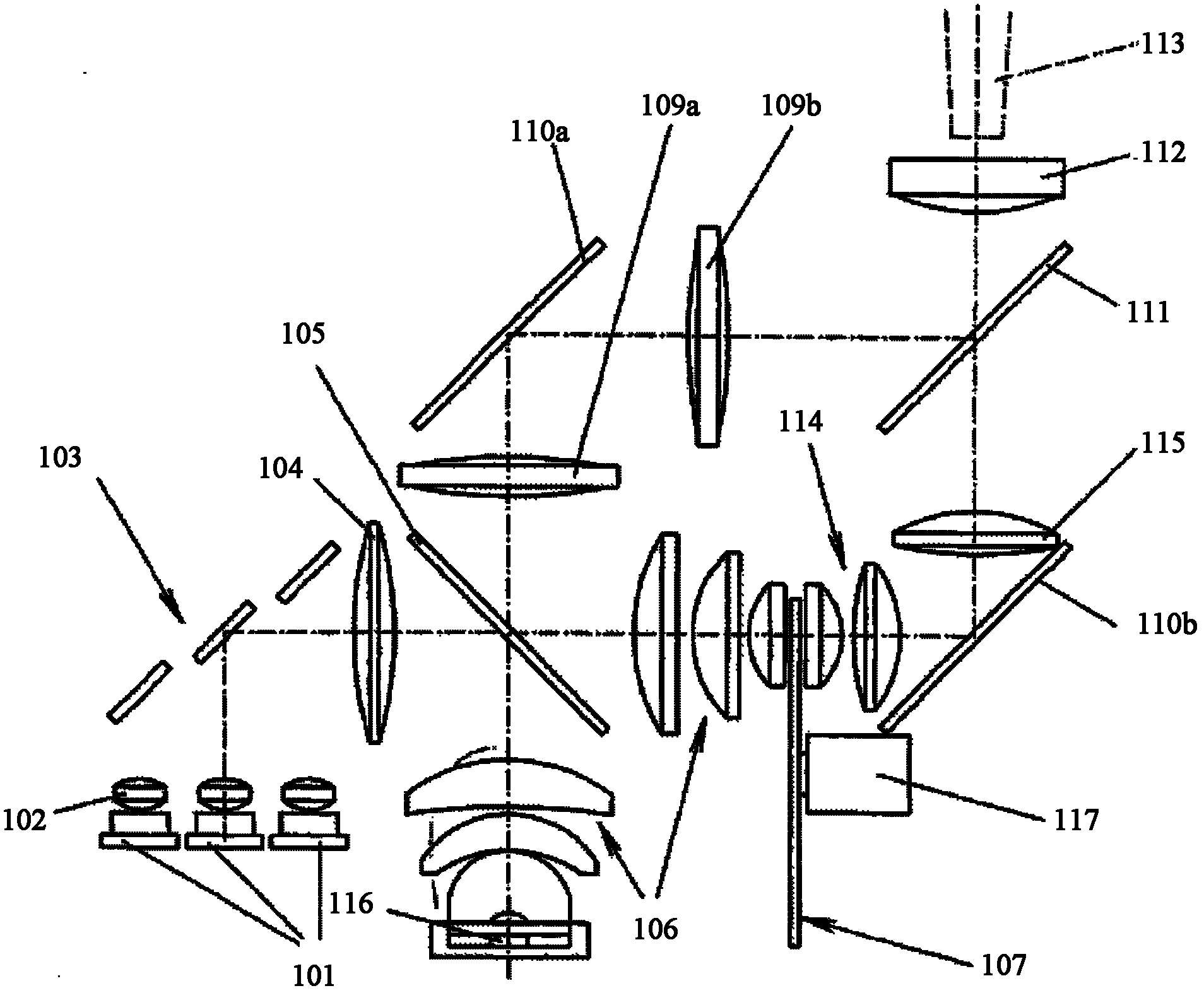
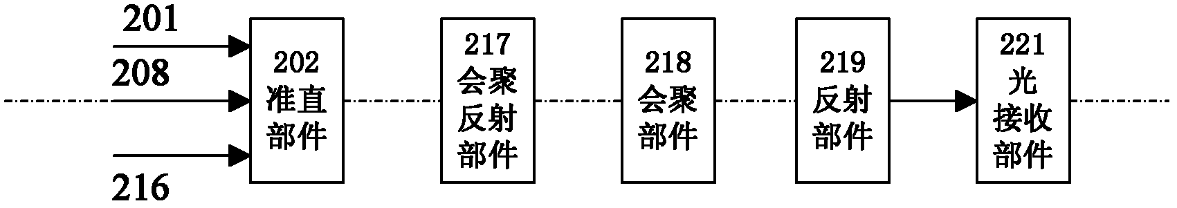
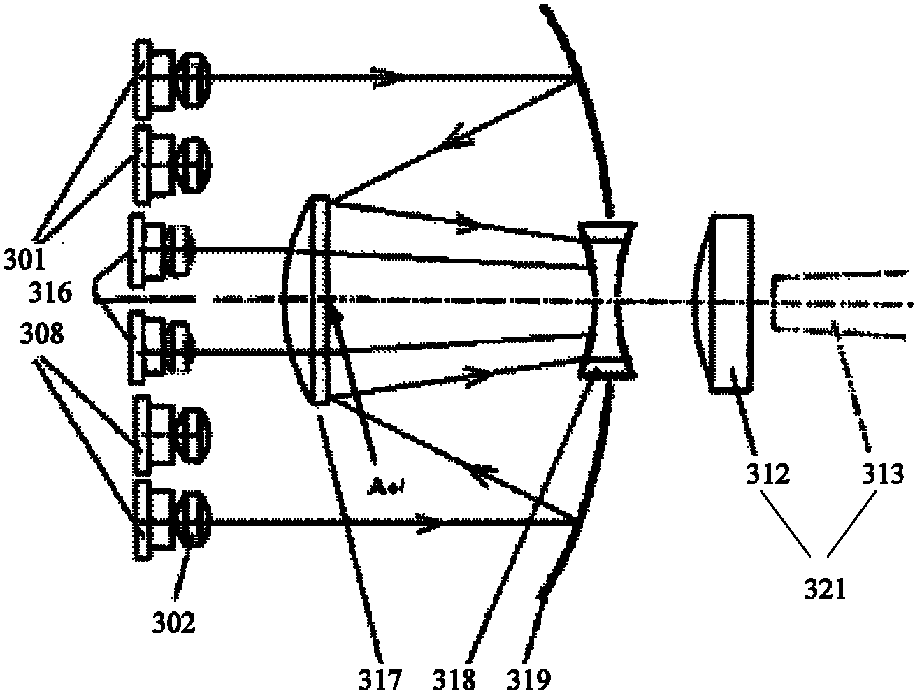
[0042] figure 2 is an exemplary schematic diagram of a light source device according to an embodiment of the present invention. Such as figure 2 As shown, the light source device in the implementation of the present invention includes: an incident light source comprising a first light source 201, a second light source 208, and a third light source 216 with different wavelengths, a collimation component 202, a converging reflection component 217, a converging component 218, a refl...


PUM


Abstract

The invention discloses a light source device, a light source generation method and a laser projection machine comprising the light source device. The light source device comprises light sources, wherein the light sources comprise a first light source, a second light source and a third light source with different wavelengths; the light source device further comprises a collimating part, a reflecting part, a converging and reflecting part and a converging part, wherein the collimating part is positioned at the ejection side of the first light source, the second light source and the third light source and is used for carrying out collimation processing on the received light sources; the reflecting part is used for reflecting the first light source and the second light source to the converging and reflecting part; the converging and reflecting part is used for carrying out reflection processing on the first light source and the second light source reflected by the reflecting part and carrying out convergence processing on the third light source after collimation processing; and the converging part is used for carrying out convergence processing on the first light source, the second light source and the third light source received so as to enable the first light source, the second light source and the third light source to enter to a light receiving part along the same direction. According to the invention, the quantity of parts in the light source device can be effectively reduced, the light path is simplified, the energy utilization ratio is increased, and the installation and the maintenance are simple.

Description

technical field [0001] The invention relates to laser projection technology, in particular to a light source device, a method for generating a light source and a laser projector including the light source device. Background technique [0002] In recent years, laser projectors have been widely used in various occasions due to their simple principle, low manufacturing difficulty, rich colors, and small visual impact, such as TV projection, miniature projection, and some commercial and entertainment systems. [0003] As we all know, an optical picture needs to be composed of at least light waves of different dominant wavelengths, such as blue, green and red light waves. Based on the current technology, usually a light source of one wavelength is used as excitation light to generate a light source of another wavelength, and then time-shared emission with light sources of other wavelengths to display various images on the projection screen. For example, the blue laser emitted by...

Claims


Application Information

Patent Timeline
Patent Type & Authority Applications(China)
IPC IPC(8): G03B21/20G03B21/14G03B21/00F21V13/04
Inventor 李巍田有良闫国枫陈昱刘风雷
Owner HISENSE
Why Eureka
Try Eureka