
Unified power flow controller based on modular multilevel converter structure

A modular multi-level, power flow controller technology, applied in the direction of flexible AC transmission system, climate change adaptation, single-network parallel feeding arrangement, etc., can solve the problem of large operating loss of the device, difficult procurement of IGBT devices, high switching frequency, etc. problems, achieve high integration, increase device capacity, and facilitate design

Inactive Publication Date: 2012-07-18
STATE GRID CORP OF CHINA +2
View PDF6 Cites 31 Cited by
  • Summary
  • Abstract
  • Description
  • Claims
  • Application Information

AI Technical Summary

Problems solved by technology

The technical difficulties of IGBT series connection with turn-off devices are mainly manifested in: affected by technology monopoly, it is difficult to purchase IGBT devices with their own short-circuit current limiting characteristics; The output harmonics require a higher switching frequency, so the operating loss of the device is relatively large
These limit the application of large-capacity UPFC

Method used


Image

  • Unified power flow controller based on modular multilevel converter structure
  • Unified power flow controller based on modular multilevel converter structure
  • Unified power flow controller based on modular multilevel converter structure

Examples


Embodiment 1

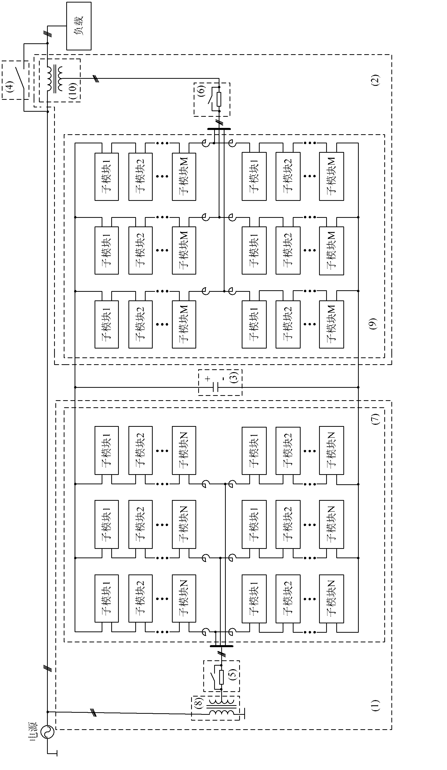
[0036] A unified power flow controller based on a modular multilevel converter structure provided by this embodiment is as follows: figure 1 As shown, it includes a static synchronous compensator 1 and a static synchronous series compensator 2; the static synchronous compensator 1 includes a starting circuit 5 and a converter 7; the static synchronous series compensator 2 includes a converter 9 and a transformer 10;

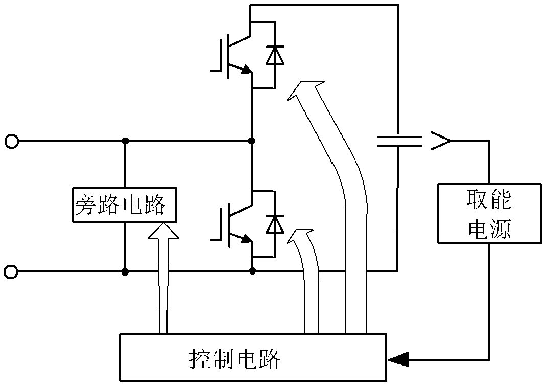
[0037] The converter 7 is composed of 3-phase six bridge arms, the six bridge arms have the same structure, and each bridge arm includes a reactor and N (N is a natural number) sub-modules with the same structure; after the sub-modules are cascaded Connect to the starting circuit 5 through a reactor; specifically, the midpoint of the half-bridge structure of the sub-module and the emitter of the lower tube IGBT are respectively used as the lead-out ends of the sub-module, which are cascaded with the front and rear modules in sequence, and then connected in series ...

Embodiment 2

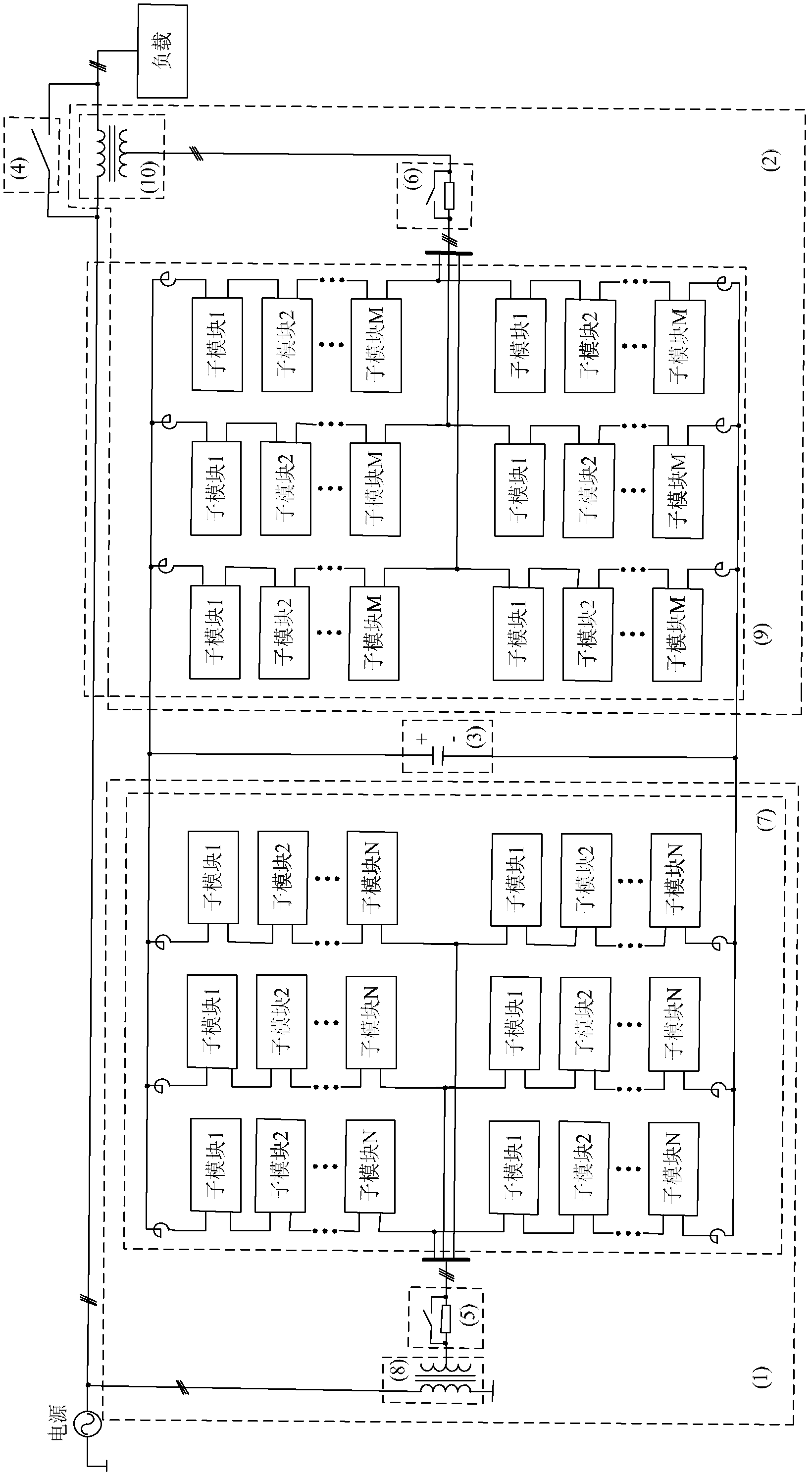
[0045] This embodiment is basically the same as Embodiment 1, but the difference lies in:

[0046] The positions of the reactors in the inverter 7 and the inverter 9 are different. The reactors in this embodiment are connected in series on the positive and negative busbar sides, such as figure 2 shown. It is used to suppress the output harmonics of the converter device.


PUM


Abstract

The invention relates to a unified power flow controller based on a modular multilevel converter structure. The unified power flow controller comprises a static synchronous compensator and a static synchronous series compensator, wherein positive and negative buses of the static synchronous compensator are connected with positive and negative buses of the static synchronous series compensator; and an output end of the static synchronous compensator and an output end of the static synchronous series compensator are respectively connected with a power grid. According to the invention, as a modular-mode cascaded form is adopted, the requirements on components are reduced; a modular design is realized, the integrated level is high, and the design is convenient; through a design on a bridge arm, an effect of individual-phase control is achieved; through using a redundancy technique, a fault unit can be bypassed, thereby improving the operation reliability of a device; in an original technique, for reducing the outputting of harmonic waves, a scheme of connecting IGBT (insulated gate bipolar translator) devices in series is usually high in switching frequency, therefore, the loss of the device is large; in the invention, a modular multilevel technique is adopted, so that the switching frequency of each component is low, but an effect of extremely high external equivalent switching frequency can be achieved, and the outputting of harmonic waves is reduced, therefore, the device is low in running loss.

Description

technical field [0001] The invention relates to the field of power electronics, in particular to a unified power flow controller based on a modular multilevel converter structure. Background technique [0002] Unified Power Flow Controller (UPFC) is the most versatile flexible alternating current transmission (FACTS) device so far. Only by changing the control law, several different functions such as parallel compensation, series compensation and shifting can be realized separately or simultaneously. The UPFC device can be regarded as a static synchronous compensator (STATCOM) device and a static synchronous series compensator (SSSC) device connected in parallel on the DC side, which can simultaneously and quickly and independently control the active power and reactive power in the transmission line. power, so that UPFC has a four-quadrant operation function that each STATCOM and SSSC device that operates independently does not have. [0003] The main circuit topology of th...

Claims


Application Information

Patent Timeline
IPC IPC(8): H02J3/38H02J3/01
CPCY02E40/16Y02A30/60Y02E40/10Y02E40/40
Inventor 王轩韩天绪刘慧文王柯武守远
Owner STATE GRID CORP OF CHINA
Learn More