
Electrical impedance tomography method based on gridding displacement model

A technology of electrical impedance tomography and imaging method, which is applied in the directions of diagnosis, diagnostic recording/measurement, medical science, etc., can solve the problem of low quality of electrical impedance tomography, and achieve the goal of highlighting substantive features, high quality, and improving reconstruction quality Effect

Active Publication Date: 2015-03-04
SEALAND TECH CHENGDU
View PDF5 Cites 0 Cited by
  • Summary
  • Abstract
  • Description
  • Claims
  • Application Information

AI Technical Summary

Problems solved by technology

[0005] The purpose of the present invention is to provide an electrical impedance tomography method based on a grid displacement model, which overcomes the defect of the prior art that the electrical impedance tomography quality is not high after the object to be measured is deformed

Method used


Image

  • Electrical impedance tomography method based on gridding displacement model
  • Electrical impedance tomography method based on gridding displacement model
  • Electrical impedance tomography method based on gridding displacement model

Examples


Embodiment

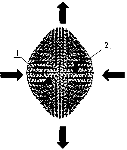
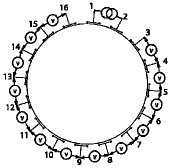
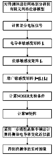
[0031] The electrical impedance tomography method based on the grid displacement model obtains the corresponding finite element grid displacement model through the object to be measured, and collects the data of the object to be measured, and calculates the differential voltage signal according to the collected data ,in, is the current voltage signal, As a reference signal, in general, It can be obtained by taking the average value after collecting multiple frames of data, so it can be approximately considered as a noise-free signal. In the present invention, the finite element grid displacement model is obtained by meshing the object to be measured. Specifically, when the object to be measured is a two-dimensional image, a triangular mesh can be used for subdivision; when the object to be measured is a three-dimensional For images, tetrahedral grids can be used for subdivision. This subdivision method not only enables fast positioning, but also facilitates imaging.

[...


PUM


Abstract

The invention discloses an electrical impedance tomography method based on a gridding displacement model, which overcomes the shortcoming that after a to-be-detected body deforms, the electrical impedance tomography quality for the to-be-detected body is poor in the prior art. The electrical impedance tomography method based on the gridding displacement model includes following steps: (1) obtaining the limit-element gridding displacement model via the to-be-detected body, acquiring data of the to-be-detected body, and calculating differential voltage signals according to the acquired data; (2) calculating a conductivity change approximate value of the to-be-detected body; and (3) displaying the calculated value in the limit-element gridding displacement model. A displayed image is a real-time differential image of the to-be-detected body. The electrical impedance tomography method utilizes the limit-element gridding displacement model to correct structural deformation of total regions of the to-be-detected body. Compared with the prior art, the electrical impedance tomography method has the advantage that the tomography quality is obviously improved.

Description

technical field [0001] The invention relates to an electrical impedance tomography method, in particular to an electrical impedance tomography method based on a grid displacement model. Background technique [0002] Electrical impedance tomography (EIT) is a non-destructive and harmless new imaging technology. EIT places electrodes on the surface of the object to be tested and injects low-frequency and low-power current, and detects the impedance distribution inside the object to be tested by detecting the voltage difference between the electrodes. Since the impedance characteristics of different biological tissues are different, using EIT technology to detect them can reflect the physiological characteristics of each biological tissue in terms of structure and function. Compared with nuclear medicine imaging techniques such as CT and MRI, EIT has the advantages of non-destructive and harmless, low cost, small size, and sensitivity to early cancer lesions. Moreover, the da...

Claims


Application Information

Patent Timeline
Patent Type & Authority Patents(China)
IPC IPC(8): A61B5/053
Inventor 戴涛蒲洋
Owner SEALAND TECH CHENGDU
Learn More