
A method to limit the one-way transport of droplets in digital microfluidic chips

A digital microfluidic and droplet technology, applied in chemical instruments and methods, laboratory containers, laboratory utensils, etc., can solve the problems of droplet misalignment, increased chip complexity and cost, increased chip stability, etc.

Inactive Publication Date: 2014-10-01
FUDAN UNIV
View PDF2 Cites 0 Cited by
  • Summary
  • Abstract
  • Description
  • Claims
  • Application Information

AI Technical Summary

Problems solved by technology

[0007] First, various environments including external vibrations and defects of the microfluidic chip itself will cause the droplet to be dislocated, that is, the external drive signal has been applied, but the droplet does not move, or moves in the opposite direction, or even runs to other places where it should not be. Arrived at
The traditional error correction method is to use capacitors or cameras to detect the position of liquid droplets in real time, which undoubtedly increases the cost of equipment, and increases the complexity of research and development for handheld devices
If there is an electrode configuration that can make the chip structurally limit the movement direction of the dead droplet, the chip’s dependence on external signals will be reduced, the chip’s stability will be increased, and the components of the droplet position detection in the device will become unimportant or even can be removed
[0008] Second, commercialized microfluidic chips are generally designed as disposable consumer goods, and cost is a key factor in whether their products can open up the market
The electrode configuration of a conventional digital microfluidic chip needs to lead out and control each electrode (see figure 4 in the article SOFT PRINTING OF DROPLETS DIGITIZED BY ELECTROWETTING), so that the number of electrodes drawn out of the chip will increase with the length of the path to control the number of droplets The linear growth of the increase, in order to arrange complex leads sometimes use multiple reticles, thus increasing the complexity and cost of the chip

Method used


Image

  • A method to limit the one-way transport of droplets in digital microfluidic chips
  • A method to limit the one-way transport of droplets in digital microfluidic chips
  • A method to limit the one-way transport of droplets in digital microfluidic chips

Examples


Embodiment Construction

[0034] The present invention will be further described below in conjunction with the accompanying drawings and embodiments, but the present invention is by no means limited to the described embodiments.

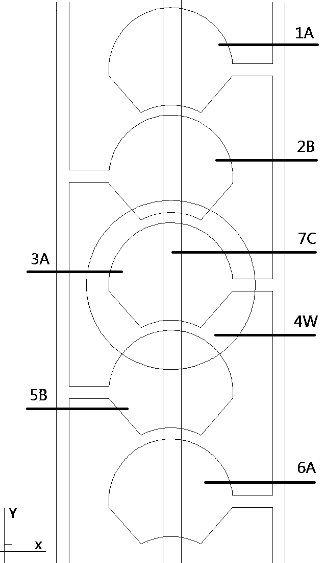
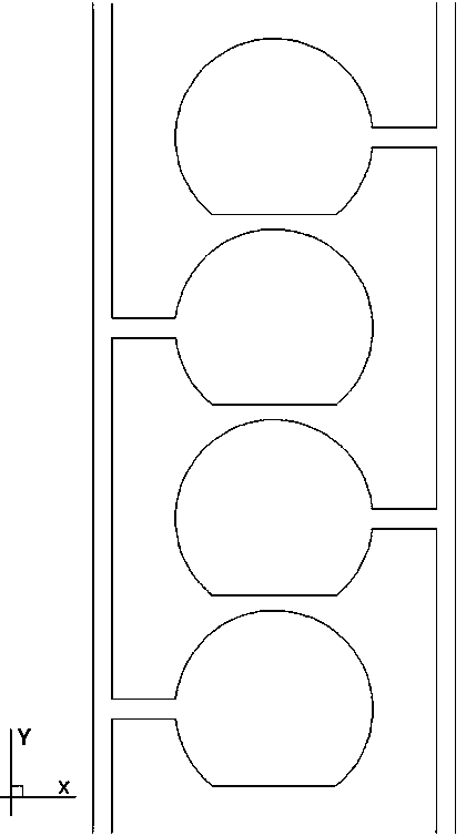
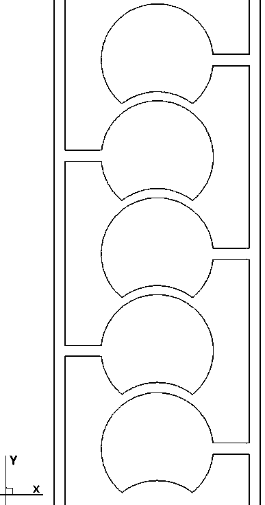
[0035] The chip is composed of the upper plate, the lower plate and the liquid droplets sandwiched between the upper and lower plates (refer to the patent, the application number is 200810038582.7 figure 1 shown). The two groups of driving electrodes A and B and their connections are in the same plane of the lower plate of the chip. The electrodes are insulated by a dielectric layer, and the electrodes and droplets are separated by a dielectric layer and a hydrophobic layer; the upper plate contains a whole electrode, called This electrode is a secondary electrode, which is directly grounded and separated from the droplet by a dielectric layer and a hydrophobic layer. figure 1 It is a structural schematic diagram of the electrode configuration of the present invention, whe...


PUM


Abstract

The invention belongs to the technical field of a digital micro-flow control chip and particularly relates to a method for limiting one-way transporting of liquid drop of the digital micro-flow control chip. The method comprises the following steps of: arranging A and B two sets of driving electrodes at interval along a transporting route of the liquid drop, wherein the electric communication between the two sets of driving electrodes meets the following condition that: the driving electrodes with the same marks are electrically communicated with each other and the driving electrodes with different marks are insulated from each other, and the structure meets the following condition: the patterns of all driving electrodes are the same or similar, a single pattern of the driving electrode is free from a symmetrical axis vertical to the transporting direction of the liquid drop; connecting an electrode C arranged along the route with constant voltage; externally applying a voltage signal and generating a potential difference changing following the time between the A and B two sets of driving electrodes; and causing the liquid drop to move along the route. According to the method provided by the invention, the dependence of the digital micro-flow control chip on the external control signal is reduced; the stability of the chip is increased and even a liquid drop position detecting unit in the equipment can be removed; and for any long transporting route of the liquid drop, only two driving electrodes are educed by the chip, so that the complexity and the cost of the digital micro-flow control chip are reduced.

Description

technical field [0001] The invention belongs to the technical field of digital microfluidic chips, and in particular relates to a digital microfluidic chip electrode configuration method that limits the unidirectional transport of liquid droplets. Background technique [0002] Digital microfluidic chip technology is a technology that microscales the preparation, detection, reaction, and movement of droplet samples on a micron-scale chip. It is mainly used in the fields of chemistry, biology, and medicine. [0003] At this stage, digital microfluidic chips mainly have the following two structures: 1. Digital microfluidic chips that do not require secondary electrodes and only have driving electrodes (patent application number 200810038582.7 figure 2 shown); 2. There is a fixed sub-electrode, which is located on the upper plate, and the driving electrode is located on the lower plate, that is, the structure of the traditional microfluidic chip (patent application number 200810...

Claims


Application Information

Patent Timeline
Patent Type & Authority Patents(China)
IPC IPC(8): B01L3/00
Inventor 李嘉方兴陈建锋周嘉
Owner FUDAN UNIV
Learn More