CNC (computerized numerical control) lathe

The technology of a numerical control lathe and a numerical control device, which is applied in the field of numerical control lathes, can solve the problem that only one end of a workpiece can be machined, etc., and achieve the effects of easy control and high work efficiency.

Inactive Publication Date: 2012-07-25
东莞市嘉坤机械有限公司
View PDF7 Cites 20 Cited by
  • Summary
  • Abstract
  • Description
  • Claims
  • Application Information

AI Technical Summary

Problems solved by technology

[0003] In order to solve the problem that the existing lathes can only process one end of the workpiece each time, the purpose of the present invention is to provide a numerically controlled lathe that can process the two ends of the same workpiece without the second clamping

Method used


Image

  • CNC (computerized numerical control) lathe
  • CNC (computerized numerical control) lathe
  • CNC (computerized numerical control) lathe

Examples


Embodiment 1

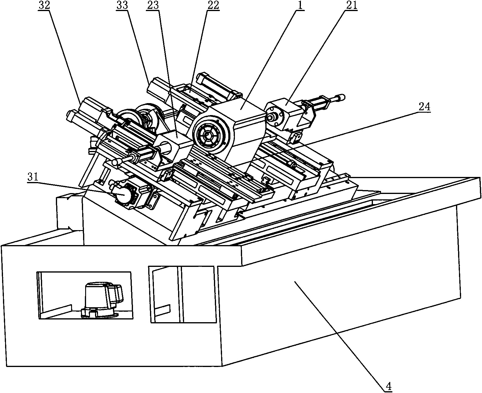
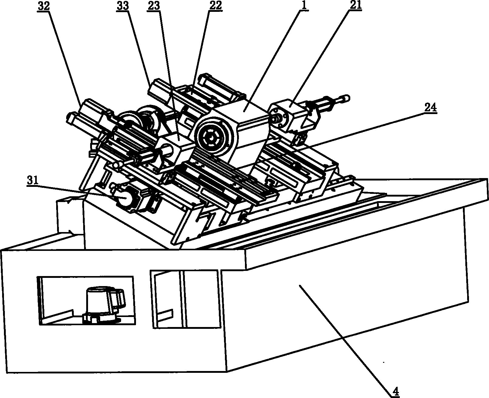
[0037] Such as figure 1 As shown, this embodiment discloses a CNC lathe, which includes: a bed part 4; a headstock device 1 arranged in the middle of the bed 4 for clamping workpieces, and the headstock device 1 adopts a double-ended headstock structure; The sliding device that is made of right top part 21, right slide plate part 22, left top part 23 and left slide plate part 24, right top part 21, right slide plate part 22 are installed on the right side of main shaft device 1, left top part 23, and The left slide part 24 is installed on the left side of the spindle device 1; the tool for processing the workpiece is installed on the left and right slide parts (22, 24), including the tool rest and the tool holder; the first X-axis servo drive device 31, the second A Y-axis servo driver 32, a second X-axis servo driver 33, and a second Y-axis servo driver (not shown in the figure, it has the same function as the first Y-axis servo driver 32 and is symmetrical in position) const...


PUM


Abstract

The invention belongs to the technical field of machining technology, in particular discloses a CNC (computerized numerical control) lathe for separately controlling and processing two ends of shaft parts at the same time, wherein the CNC lathe comprises a main spindle box which is arranged in the middle of the lathe body, left and right sliding plate devices which are respectively arranged at the two sides of the main spindle box, a servo driving device, a CNC tool which is installed on the sliding plate devices for processing workpieces and a dual CNC device. The CNC lathe provided by the invention can not only reduce workpiece clamping times and improve work efficiency but also can reduce second clamping error, ensure consistency of workpiece processing and improve workpiece accuracy.

Description

technical field [0001] The invention belongs to the technical field of mechanical processing, and in particular relates to a cutting machine tool, in particular to a numerically controlled lathe which can separately control and process the two ends of a shaft part at the same time. Background technique [0002] At present, lathes for processing shaft parts first clamp the processed shaft parts once, and can only process one end of the workpiece. If two ends of a shaft are to be processed on a common lathe, one end must be processed first, then the shaft is removed and turned around, and after the second clamping, the other end of the shaft is processed. Such processing machine tools not only have low processing efficiency and high labor intensity for workers, but also have poor consistency, and it is difficult to guarantee processing accuracy. At the same time, when clamping, it is difficult to control the clamping force to be consistent with the clamping position, which ma...

Claims


Application Information

Patent Timeline
Patent Type & Authority Applications(China)
IPC IPC(8): B23B7/14B23B19/00
Inventor 张子枫
Owner 东莞市嘉坤机械有限公司
Why Eureka
Try Eureka