Tool holder for piping end part machining

A pipe material and tool holder technology, which is applied in the field of pipe material tool holders and tool holders for pipe end processing, can solve the problems of low machining accuracy of pipe material ring grooves, increased pipe material circular runout, and low adjustment accuracy. , to achieve the effect of reducing moment, reducing radial runout and increasing support area

Active Publication Date: 2017-09-15
山东中宝金属材料有限公司
View PDF8 Cites 2 Cited by
  • Summary
  • Abstract
  • Description
  • Claims
  • Application Information

AI Technical Summary

Problems solved by technology

[0002] In the prior art, the conventional method of processing the ring groove at the end of the pipe is to use a three-jaw chuck to clamp the pipe, and then the motor drives the three-jaw chuck to rotate along its central axis, and then the cutting tool such as a turning tool Carry out ring groove processing on the surface of the pipe material. Because the pipe material moves and the tool does not move in this traditional pipe material processing method, the spiral groove processing has requirements for the shape of the pipe material, and the machining accuracy of the pipe material ring groove is not high; and In recent years, the appearance of the grooving machine has effectively solved the technical problems of the traditional method of grooving at the end of the pipe by fixing the pipe material and rotating the cutter. For example, a pipe grooving machine is disclosed in the Chinese utility model patent CN203356756U. The structure of the rotary groove mechanism includes an inner cylinder core, at least one rotary groove cutter is movably installed at one end of the inner cylinder core, and the other end is hinged with the piston rod of the hydraulic cylinder. The inner cylinder core is driven by a motor, and the outer cylinder sleeve Placed on the inner cylinder core, the outer cylinder is hinged on a connecting piece, the connecting piece is fixed on the piston rod of the hydraulic cylinder, and the spiral groove cutter and the outer cylinder are formed with wedge surfaces that cooperate with each other
The technical problems existing in this technical solution are: 1. Pipe material whirling processing generally adopts a clamp to clamp the pipe material, and at the same time, the end of the pipe material is whirled by a rotary knife. At this time, the pipe material is only There is a clamping point without other support points, the force generated on the processing station when the rotary knife processes the tube material will not only increase the circular runout of the tube material, but also the torque on the tube material clamping point will easily affect the tube material The deformation of the material (the stress point is a moment away from the clamping point), especially for some pipe materials with thinner diameters and materials that are easily deformed; The axial movement of the pipe material meets the requirements of the processing committee, so the clamp must be loosened every time, and the clamping position of the pipe material must be manually adjusted to meet the rotation grooves of each station. At this time, there are problems such as low adjustment accuracy and long time consumption. Defects; 3. The lubricating oil used to lubricate the tool during pipe material grooving is easy to splash due to the effect of rotating centrifugal force, which is not easy to recycle

Method used


Image

  • Tool holder for piping end part machining
  • Tool holder for piping end part machining
  • Tool holder for piping end part machining

Examples


Embodiment Construction

[0022] In order to make the object, technical solution and advantages of the present invention clearer, the present invention will be further described in detail below in conjunction with the accompanying drawings and embodiments. It should be understood that the specific embodiments described here are only used to explain the present invention, not to limit the present invention.

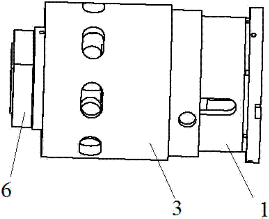
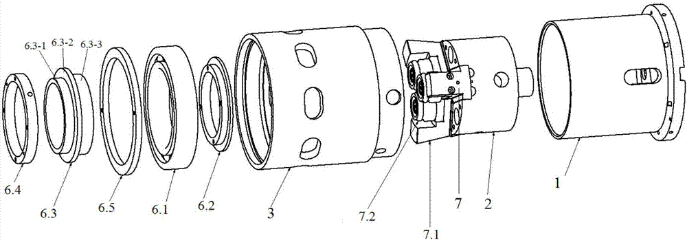
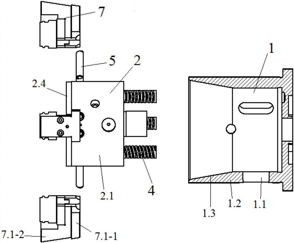
[0023]It can be seen from the structural schematic diagram of a tool holder for pipe end processing shown in the accompanying drawings that the tooling of the present invention includes a cutter head sliding seat 1, and a hob support is coaxially slid and connected in the cutter head sliding seat 1 Seat 2, the outer coaxial sliding sleeve of the cutter head sliding seat 1 has a sliding sleeve 3; a first compression spring 4 is arranged between the cutter head sliding seat 1 and the hob support seat 2, and the first compression spring 4 is arranged along the cutter head sliding seat 1 The axial arra...


PUM


Abstract

The invention discloses a fixture for piping end port forming. The fixture comprises a tool bit slide seat, wherein a hobbing cutter support seat is connected in the tool bit slide seat in a manner of coaxial slide fit, a rotating cutter assembly is arranged on the end part of the hobbing cutter support seat, and mutually-matched wedge surfaces are formed on the rotating cutter assembly and the tool bit slide seat; a slide sleeve sleeves outside the tool bit slide seat in a manner of coaxial slide; a waist-shaped guide hole formed in the axial direction of the tool bit slide seat is formed in the sidewall of the tool bit slide seat; the hobbing cutter support seat and the slide sleeve realize mutual connection through a pin shaft penetrating through the waist-shaped guide hole; and a location assembly used for ensuring the coaxiality of piping machining is arranged on the end part of the slide sleeve. The tool holder disclosed by the invention is convenient to use, high in machining accuracy, stable in control on the coaxiality of pipelines during machining, and higher in location accuracy, more convenient and faster relative to traditional machinery.

Description

technical field [0001] The invention relates to a pipe material cutter holder, which belongs to the technical field of pipe end forming equipment, in particular to a pipe material end processing tool holder. Background technique [0002] In the prior art, the conventional method of processing the ring groove at the end of the pipe is to use a three-jaw chuck to clamp the pipe, and then the motor drives the three-jaw chuck to rotate along its central axis, and then the cutting tool such as a turning tool Carry out ring groove processing on the surface of the pipe material. Because the pipe material moves and the tool does not move in this traditional pipe material processing method, the spiral groove processing has requirements for the shape of the pipe material, and the machining accuracy of the pipe material ring groove is not high; and In recent years, the appearance of the grooving machine has effectively solved the technical problems of the traditional method of grooving...

Claims


Application Information

Patent Timeline
Patent Type & Authority Applications(China)
IPC IPC(8): B23B29/00B23D79/00B23Q3/00
CPCB23B29/00B23D79/00B23Q3/00
Inventor 熊震左江桥郑红讯李威杜晓峰杨韦闻华浩刘佳
Owner 山东中宝金属材料有限公司
Why Eureka
Try Eureka