Double-tube-sinking and inner-tube-drawing bored cast-in-place pile construction method and application

A technology of cast-in-situ piles and inner pipes, applied in sheet pile walls, foundation structure engineering, construction, etc., can solve the problems of large pile end area, reduced construction efficiency, and difficult pile sinking, and achieve good pile quality and wide application range Effect

Inactive Publication Date: 2012-07-25
SHANGHAI ZHENZHONG MACHINERY MFG
View PDF6 Cites 9 Cited by
  • Summary
  • Abstract
  • Description
  • Claims
  • Application Information

AI Technical Summary

Problems solved by technology

But this method is to completely squeeze the soil, and if the soil accumulation effect is serious, the road buildings will be squeezed and cracked; secondly, the movable pile tip of the pipe pile will be closed when the pile tip sinks, so that the pile end area is large, the end resistance is large, and the sinking Pile difficult
Usually, the pile diameter of the vibratory sinking tube grouting pile is small, generally less than 0.5m in diameter; in addition, when the steel cage is placed in the sinking tube and the sinking tube is pulled up by vibration after pouring concrete, sometimes the pile tip cannot be opened or is not completely

Method used


Image

  • Double-tube-sinking and inner-tube-drawing bored cast-in-place pile construction method and application
  • Double-tube-sinking and inner-tube-drawing bored cast-in-place pile construction method and application
  • Double-tube-sinking and inner-tube-drawing bored cast-in-place pile construction method and application

Examples


Embodiment Construction

[0026] The present invention will be further described below in conjunction with accompanying drawing, and the structure and principle of this device are very clear to those skilled in the art.

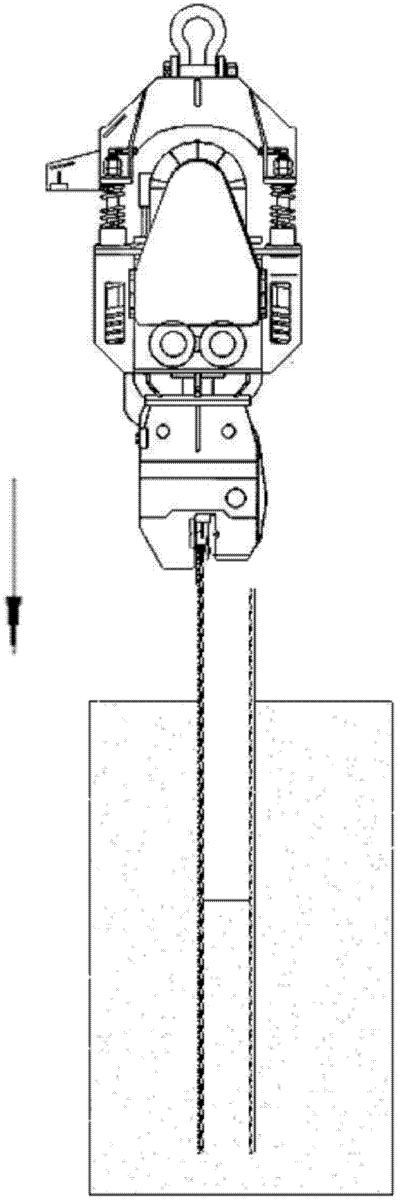
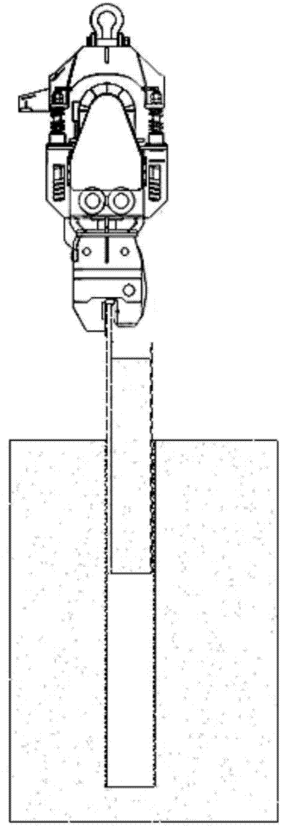
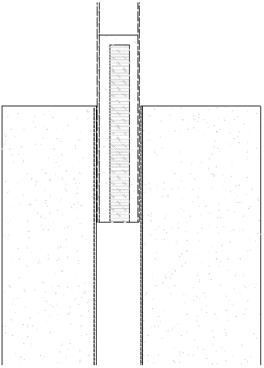
[0027] The cast-in-situ pile construction method of sinking double pipes and pulling inner pipes to form holes in the present invention includes a construction method of sinking double pipes and pulling inner pipes to form holes and pouring piles and a construction method of sinking double pipes and pulling inner pipes to complete pile extraction and pile planting. The main equipment system of this construction method includes a vibrating hammer with adjustable eccentric moment, a column clamp, a double-tube steel pipe with a gap of 5-10mm between the inner and outer tubes, and a special column frame or lifting crane. Its specific construction method steps are:

[0028] 1. As attached figure 1 As shown, the inner tube is sleeved in the outer tube, and the inner and outer tubes are cl...


PUM


Abstract

The invention relates to the technical field of piling construction, and mainly relates to a double-tube-sinking and inner-tube-drawing bored cast-in-place pile construction method and application. The construction method adopts an eccentric moment-adjustable vibrating hammer, a pile gripper, inner tubes, outer tubes and a piling rack or a hoisting crane. The construction method includes steps that the inner tubes and the outer tubes are clamped by the pile gripper at first, the vibrating hammer vibrates and stops vibrating after sinking to the required depth, a pile clamping method is changed so that the pile gripper only clamps the inner tubes, a winch is started so that the vibrating hammer draws the inner tubes in a vibration-free state until the inner tubes are thoroughly drawn out, soil in the inner tubes cannot be poured out when the inner tubes are statically drawn due to effects of friction force, then the piling rack or the hoisting crane moves so that the inner tubes are separated from openings of the outer tubes, the vibrating hammer is started to vibrate, the soil in the inner tubes is continuously poured out in a vibration state until the total soil is poured out, reinforcement cages are placed in the outer tubes sunken into the soil, concrete is fully filled in the reinforcement cages, finally, the outer tubes are clamped by a fixture, the vibrating hammer is started, the outer tubes are drawn out by the aid of the vibration effect of the vibrating hammer, and simultaneously, a pile is formed. The double-tube-sinking and inner-tube-drawing bored cast-in-place pile construction method and the application have the advantages that the structure is novel, and construction efficiency is high.

Description

[technical field] [0001] The invention relates to the technical field of piling construction, and mainly relates to a construction method of sinking double pipes and pulling inner pipes to form holes and its application. [Background technique] [0002] As we all know, when ground buildings are built on the ground, the ground will bear considerable pressure. In order to ensure the stability of the building, it must be ensured that the ground has sufficient strength to resist pressure. Therefore, it is necessary to reinforce the ground bearing the building or improve the bearing capacity of the ground. Therefore, the method of piling on the foundation is adopted to make most of the weight of the building be transmitted to a deep position below the ground through piles, so as to improve the bearing capacity of the building. [0003] There are typically two methods of hole-forming cast-in-place piles in the existing pile-driving technology. The first is vibratory sinking tube-in...

Claims


Application Information

Patent Timeline
IPC IPC(8): E02D11/00E02D5/38
Inventor 曹荣夏曹摩西曹小骥
Owner SHANGHAI ZHENZHONG MACHINERY MFG
Why Eureka
Try Eureka