Inspection well

A technology for inspection wells and shafts, applied in the field of inspection wells, can solve the problems of low compressive strength of inspection wells, easy leakage and construction difficulty, etc., and achieve the effects of avoiding sewage leakage, light weight and long service life

Inactive Publication Date: 2012-07-25
HARBIN GOLDEN SUNSHINE PIPE IND
View PDF8 Cites 8 Cited by
  • Summary
  • Abstract
  • Description
  • Claims
  • Application Information

AI Technical Summary

Problems solved by technology

[0003] The purpose of the present invention is to solve the problems of low compressive strength, easy leakage and difficult construction in existing inspection wells, and to provide an inspection well

Method used


Image

  • Inspection well
  • Inspection well
  • Inspection well

Examples


specific Embodiment approach 1

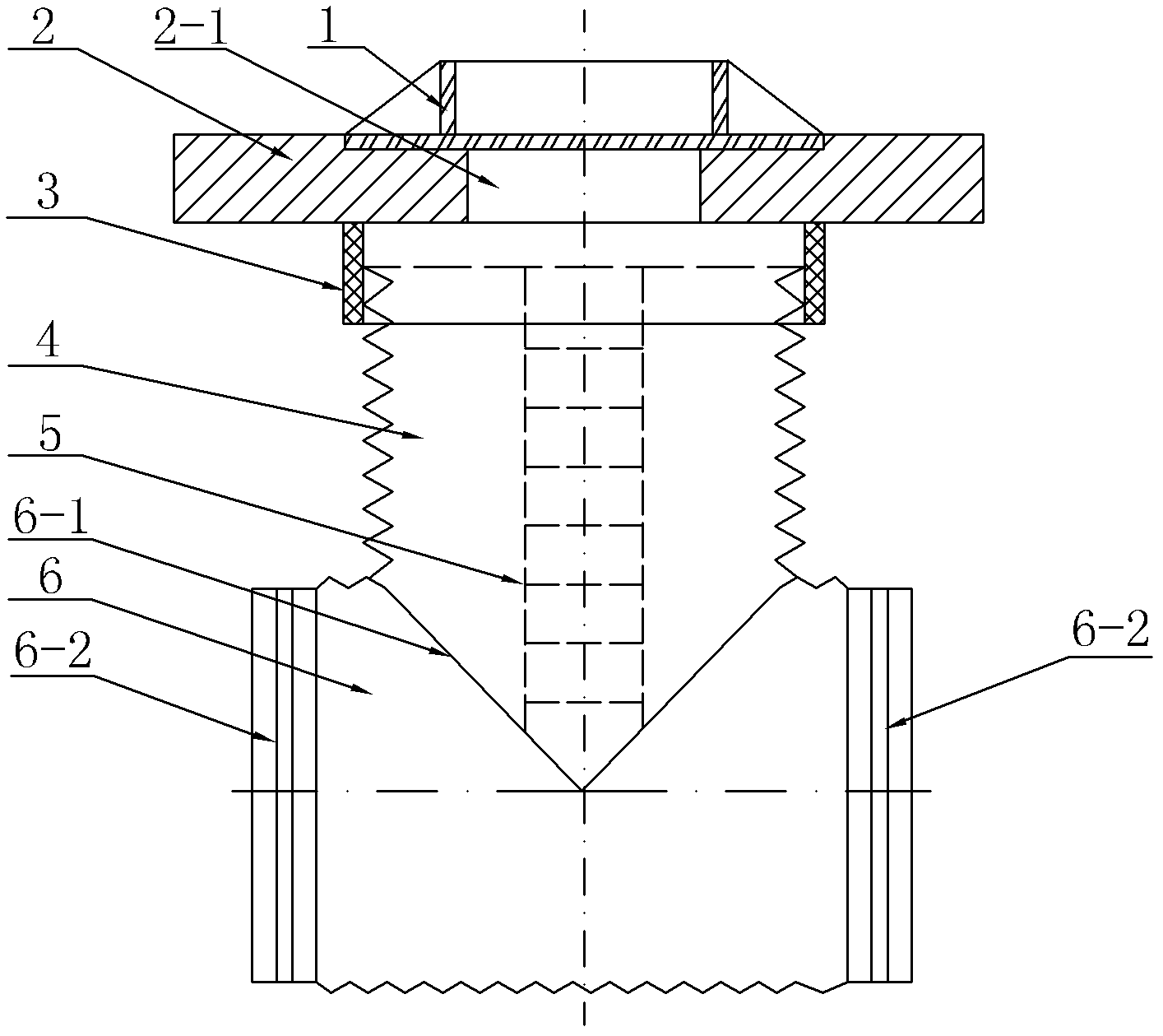
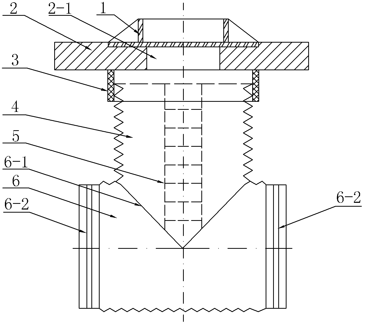
[0007] Specific implementation mode one: combine figure 1 with figure 2 Describe this embodiment, an inspection well of this embodiment includes a well cover 1 and a base 2, the well cover 1 is embedded on the base 2, and the middle part of the base 2 is provided with a wellhead 2-1, which also includes a retaining ring 3, a well shaft 4 and the receiving pipe 6, the wellbore 4 is a bellows made of metal, the receiving pipe 6 is a bellows made of metal, the inner and outer walls of the wellbore 4 and the inner and outer walls of the receiving pipe 6 have The galvanized layer, the wellbore 4 is vertically set, the retaining ring 3 is set on the wellbore 4, the base 2 is set on the upper end surface of the retaining ring 3, the wellhead 2-1 and the wellbore 4 are coaxially arranged, and the pipe wall of the receiving pipe 6 There is a connecting hole 6-1 on the top, and the lower end of the wellbore 4 is set on the connecting hole 6-1 of the receiving pipe 6. The wellbore 4 an...

specific Embodiment approach 2

[0009] Specific implementation mode two: combination figure 1 To illustrate this embodiment, the inspection well described in this embodiment further includes a foot ladder 5 , and a foot ladder 5 is provided on the inner side wall of the shaft 4 . With such arrangement, it is convenient to use, convenient to inspect and dredge the pipeline, and convenient for construction work. Others are the same as in the first or second embodiment.

specific Embodiment approach 3

[0010] Specific implementation mode three: combination figure 1 To describe this embodiment, the cross-sectional shape of the connecting hole 6-1 on the receiving pipe 6 described in this embodiment is triangular. In this way, the fluidity of the sewage is good and the resistance is small, which meets the design requirements and actual needs. In this embodiment, the connection hole with a triangular cross-sectional shape and the wellbore has a transitional arc, and the others are the same as the specific embodiment 1 or 2.

[0011] work process

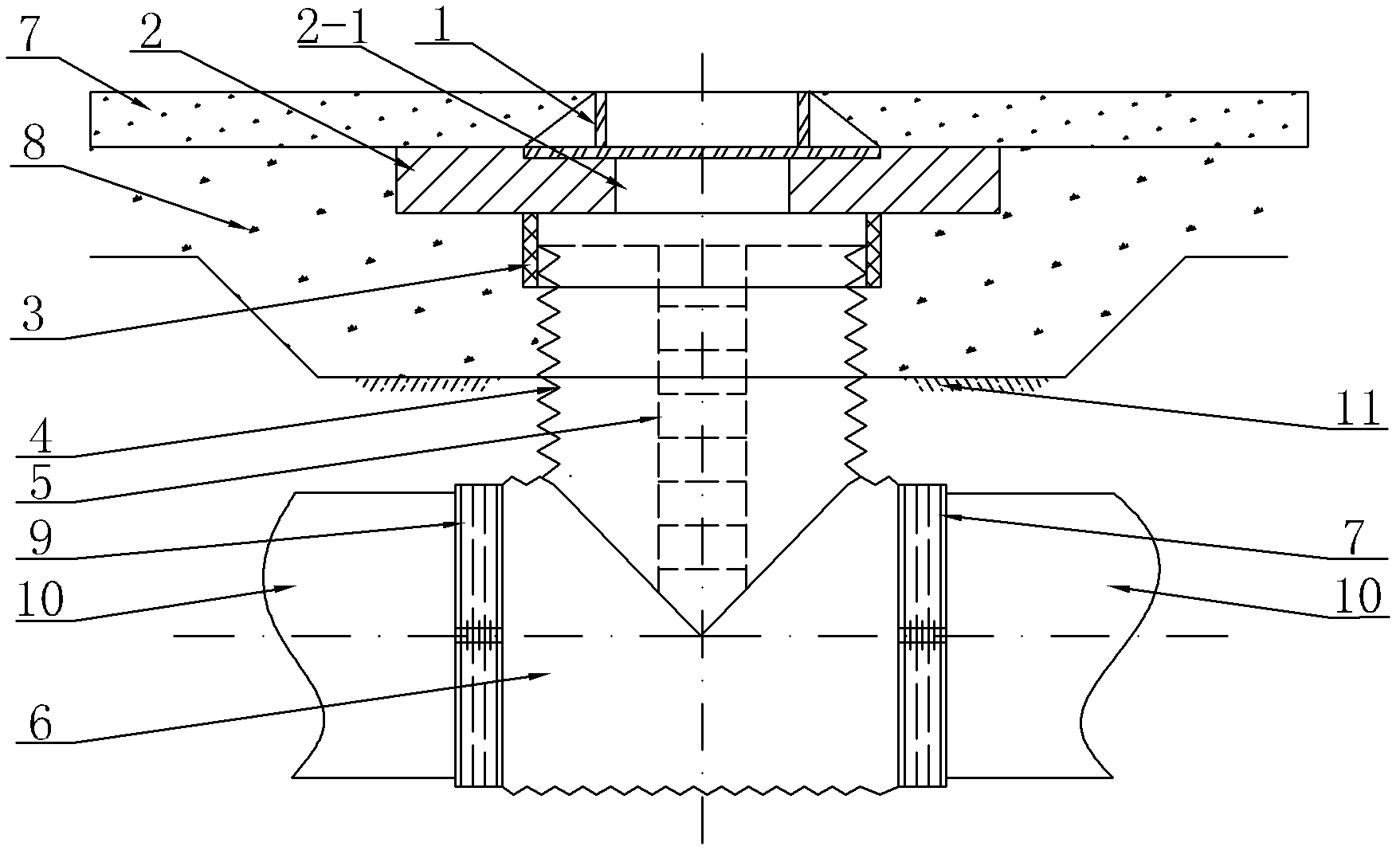
[0012] combine figure 1 with figure 2 Illustrate the working process of the present invention. When the inspection well of the present invention is in use, place the integrally made receiving pipe 6 and part of the pipe section of the shaft 4 below the backfill 11, and place the nozzles 6-2 at both ends of the receiving pipe 6 respectively. It is connected with the pipeline 10 buried underground through the clamp 9, and the retain...


PUM


Abstract

The invention relates to an inspection well, in particular relates to an inspection well for maintaining a pipeline and removing sludge. The inspection well belongs to the field of municipal engineering and solves the problems of low compression strength, easiness for leakage and large construction difficulty of the conventional inspection well. The inspection well comprises a well cover and a base, wherein the well cover is nested on the base; and a well opening is arranged at the middle of the base. The inspection well further comprises a retainer ring, a well cylinder and a bearing pipe; the well cylinder is a corrugated pipe made of metal; the bearing pipe is another corrugated pipe made of the metal; zinc plated layers are respectively arranged on the inner wall surface and the outer wall surface of the well cylinder and the inner wall surface and the outer wall surface of the bearing tube; the retainer ring is sleeved on the well cylinder; the base is arranged on the upper end surface of the retainer ring; the well opening and the well cylinder are coaxially arranged; a connection hole is formed on the pipe wall of the bearing pipe; the lower end of the well cylinder is arranged on the connection hole of the bearing tube; the well cylinder and the bearing pipe are integrally manufactured; and tube openings at both ends of the bearing tube are detachably connected with a pipeline which is pre-embedded under the ground. The inspection well is used for drainage pipelines in the municipal engineering.

Description

technical field [0001] The invention relates to an inspection well, in particular to an inspection well for repairing pipelines and removing sludge, and belongs to the field of municipal engineering. Background technique [0002] In the drainage and sewage pipeline system of municipal engineering, the inspection well is an important equipment, which plays an important role in inspecting and dredging the pipeline. However, the existing inspection wells mostly use brick wells or plastic wells. The well is prone to sewage leakage during use, causing secondary pollution of groundwater, and it is easy to collapse under heavy loads, with low compressive strength and serious damage. Moreover, the construction is difficult and the quality stability is poor; the compressive strength of plastic wells lower, resulting in reduced service life. Contents of the invention [0003] The purpose of the present invention is to solve the problems of low compressive strength, easy leakage and...

Claims


Application Information

Patent Timeline
Patent Type & Authority Applications(China)
IPC IPC(8): E02D29/12
Inventor 闫峰赵志航
Owner HARBIN GOLDEN SUNSHINE PIPE IND
Why Eureka
Try Eureka