
Downward hole pressure measuring device and process

A pressure measurement device and pressure measurement technology, which is applied in the direction of measurement, wellbore/well components, earthwork drilling and production, etc., can solve the problems of difficulty in measuring gas pressure in downholes, long measurement time, and poor reliability, so as to prevent the sealing material Effects of liquid leakage, measurement of gas pressure, and accurate gas pressure

Inactive Publication Date: 2012-07-25
HENAN POLYTECHNIC UNIV
View PDF6 Cites 14 Cited by
  • Summary
  • Abstract
  • Description
  • Claims
  • Application Information

AI Technical Summary

Problems solved by technology

In the practice of gas prevention and control, a variety of gas pressure measurement devices and techniques have been developed, but they all have the characteristics of long measurement time, poor reliability, good effect on upward drilling, and poor effect on downward drilling. The technical means of sealing the hole shows that there are still many problems, especially in the condition that the pressure measurement location of the coal mine does not meet the conditions of the upward hole, and the gas pressure measurement of the downward hole is difficult.

Method used


Image

  • Downward hole pressure measuring device and process
  • Downward hole pressure measuring device and process
  • Downward hole pressure measuring device and process

Examples


Embodiment

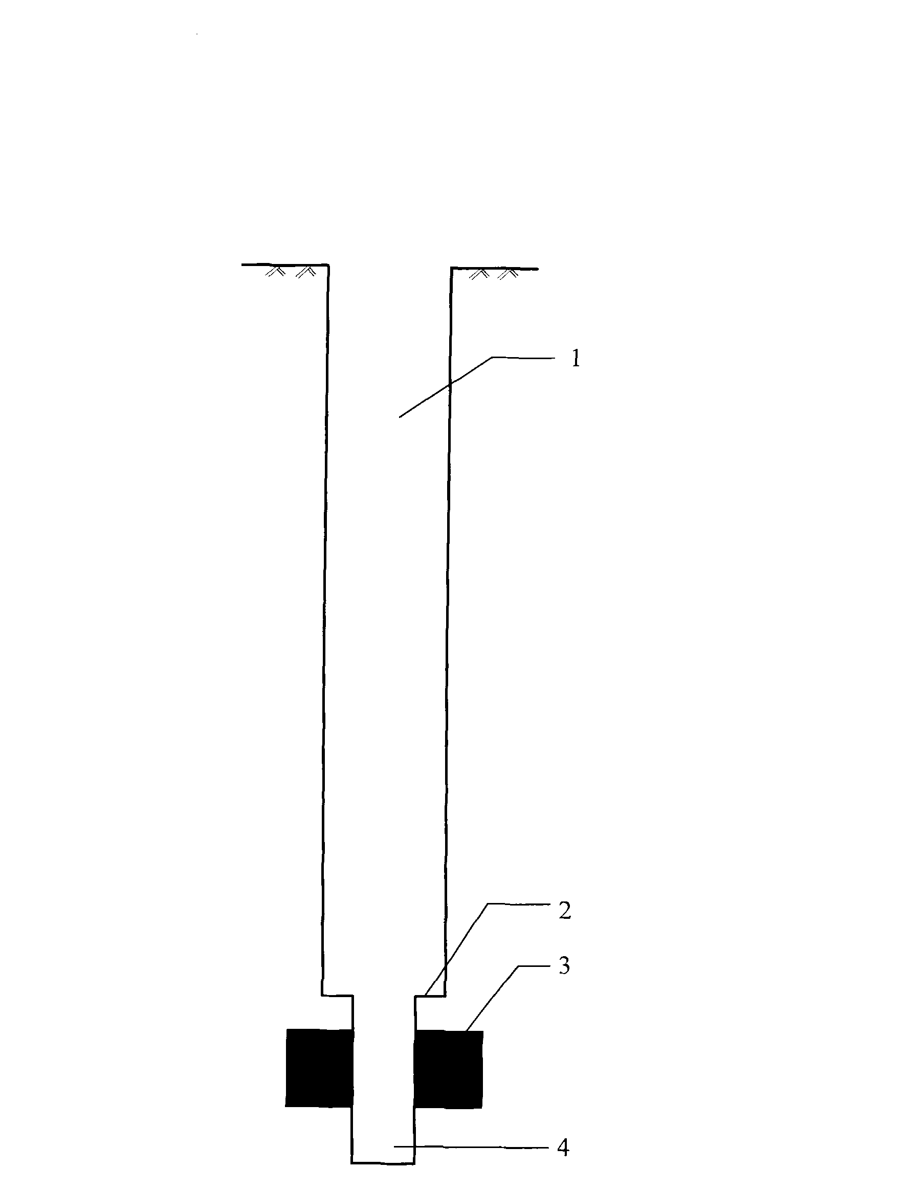
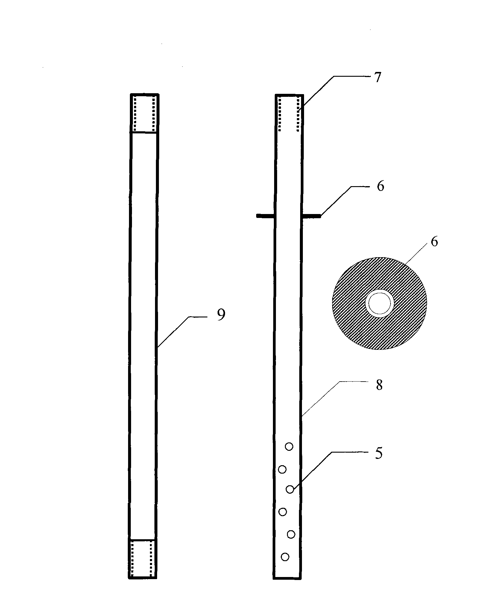
[0017] Example: see figure 1 It is a schematic diagram of the drilling structure. The characteristics of the drilling structure for the pressure measurement of the down hole in the coal mine are that the drilling with a diameter of ¢108mm is first constructed, and the drilling is stopped at a position 1-2m away from the measured coal seam, and the drill bit of ¢75mm is used to continue drilling to the bottom of the coal seam. Stop drilling at 3-4m, flush the borehole, drain the water in the borehole, and complete the pressure measurement drilling construction. figure 2 Schematic diagram of the implementation of the piezometric tube for the downhole. As shown in the figure, the piezometric tube is made of galvanized iron pipe with a diameter of 4 inches (industrial standard DN15), each of which is 2m long (easy to carry and install underground). Connection with pipe hoops; the first circular baffle plate of the pressure measurement common pipe is ¢105mm, the installation posit...


PUM

PropertyMeasurementUnit
Diameteraaaaaaaaaa
Heightaaaaaaaaaa

Abstract

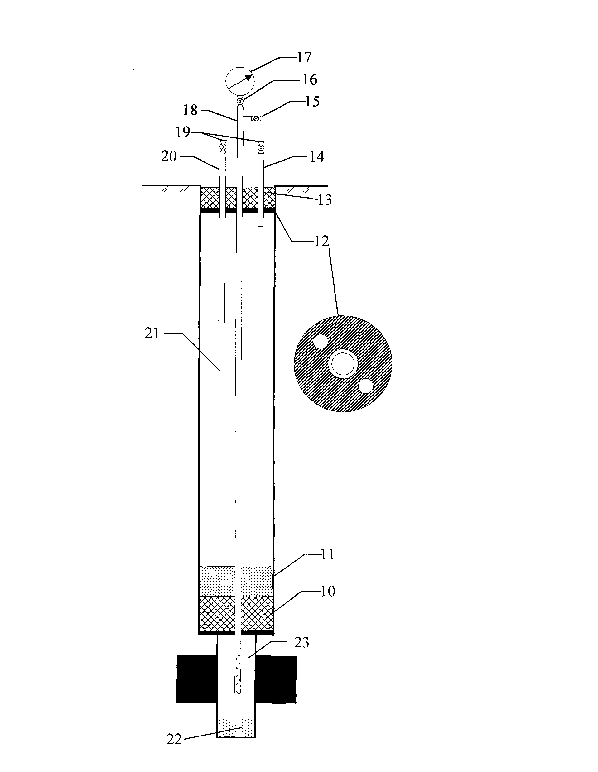
The invention provides a downward hole pressure measuring device and a downward hole pressure measuring process. The downward hole pressure measuring device comprises a variable diameter hopper type drill hole, a drilling cuttings settling chamber, a pressure measuring shock tube, a pressure measuring tube, a grouting tube and a return tube, wherein the pressure measuring shock tube is provided with a front baffle and a ventilating hole; the pressure measuring tube sequentially passes through the front baffle, expansion materials, cotton yarns, sand stones and orifice expansion materials; a high-precision pressure gauge is installed at a part of the pressure measuring tube exceeding an orifice; and the grouting tube and the return tube sequentially pass through the orifice expansion materials. According to the downward hole pressure measuring device, as a downward hole is sealed by using the combination mode of a round baffle, the expansion materials, the sand stones, cement mortar, the expansion materials and an orifice sealing baffle, the amount of the cement mortar leaking to a pressure measuring chamber can be effectively reduced, a grouting chamber which is sealed by using double sealing baffles can improve the grouting pressure and play the role of penetration sealing on hole wall cracks. As the drilling cuttings settling chamber is reserved in the pressure measuring chamber, the pressure measuring chamber can be ensured not to be blocked so as to accurately measure the coal bed gas pressures. The downward hole pressure measuring device has the characteristics of simplicity in structure, low cost and convenience for underground operation and is easy to install.

Description

technical field [0001] The invention relates to a coal mine underground gas pressure sealing hole measurement technology, which belongs to the technical field of coal. Background technique [0002] Coal seam gas pressure is one of the basic gas parameters of coal seam, which has important practical significance for the research and analysis of coal and gas outburst hazards, mine gas gushing control, mine gas drainage, etc. In the practice of gas prevention and control, a variety of gas pressure measurement devices and techniques have been developed, but they all have the characteristics of long measurement time, poor reliability, good effect on upward drilling, and poor effect on downward drilling. The technical means of sealing holes shows that there are still many problems, especially when the pressure measurement location in the coal mine does not meet the conditions of the upward hole, it is difficult to measure the gas pressure of the downward hole. Contents of the in...

Claims


Application Information

Patent Timeline
IPC IPC(8): E21B47/06E21B33/13
Inventor 吕闰生倪小明张子戌刘高峰袁军伟
Owner HENAN POLYTECHNIC UNIV
Learn More