Axial flow ventilator capable of synchronously adjusting blades

An axial flow fan, synchronous adjustment technology, applied in mechanical equipment, machines/engines, liquid fuel engines, etc., can solve the problems of unbalanced service life, time-consuming and labor-intensive impellers, etc., to extend service life, improve anti-corrosion performance, and reduce vibration. Effect

Inactive Publication Date: 2012-07-25
山西渝煤科安运风机有限公司
View PDF6 Cites 4 Cited by
  • Summary
  • Abstract
  • Description
  • Claims
  • Application Information

AI Technical Summary

Problems solved by technology

[0004] In order to solve the problem of time-consuming and labor-intensive adjustment of the blade installation angle of the existing axial flow fan and the problem that the impeller imbalance is likely to affect the service life, the present invention provides an axial flow fan with synchronous blade adjustment

Method used


Image

  • Axial flow ventilator capable of synchronously adjusting blades
  • Axial flow ventilator capable of synchronously adjusting blades
  • Axial flow ventilator capable of synchronously adjusting blades

Examples


Embodiment Construction

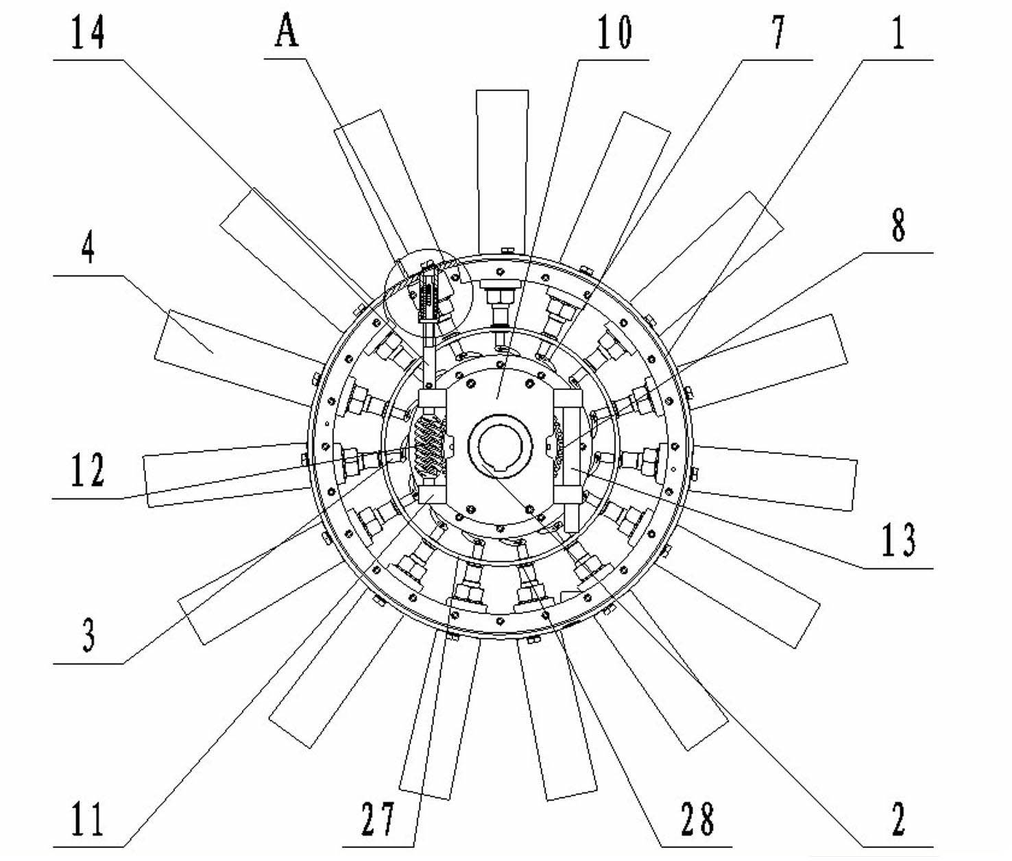
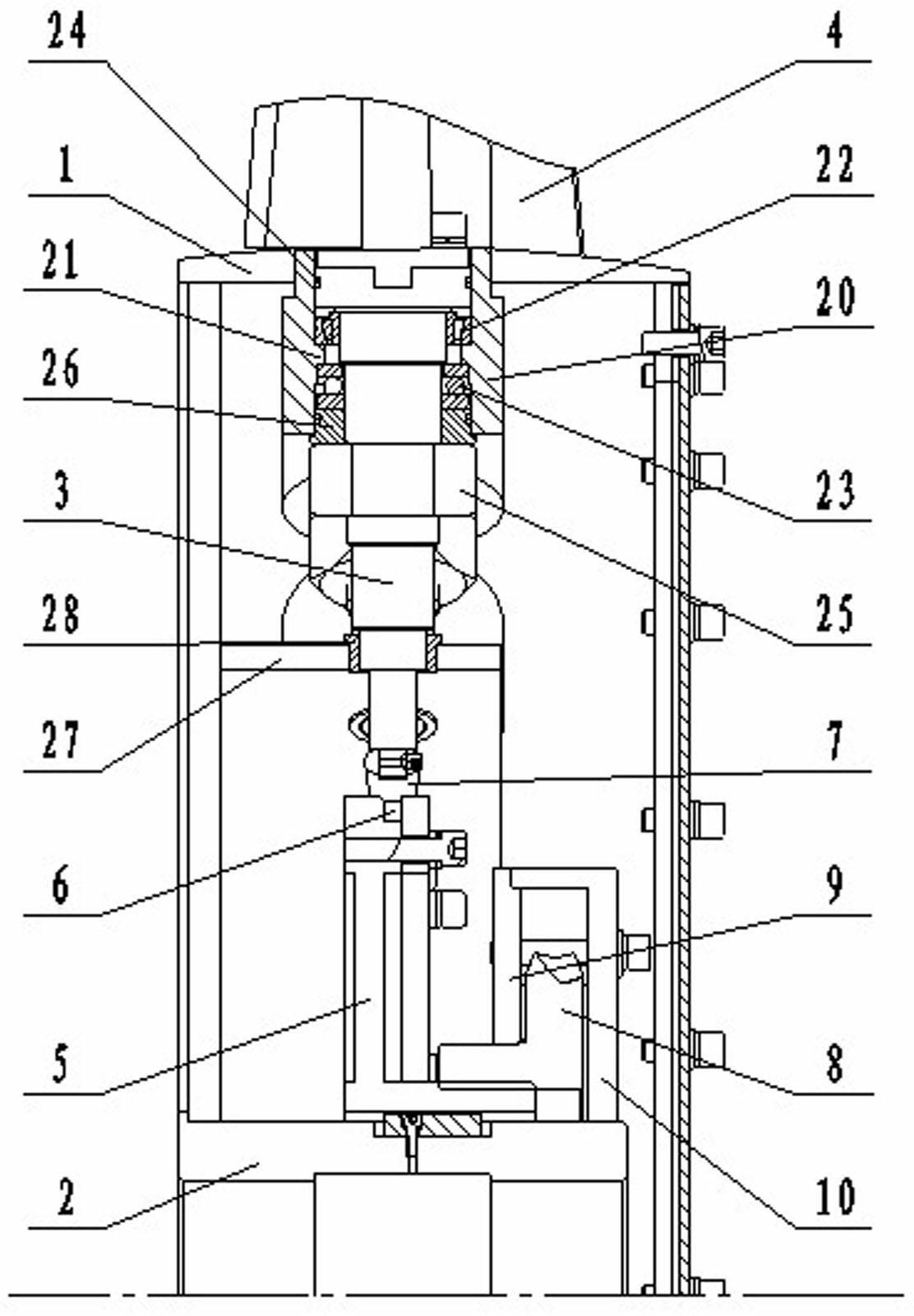
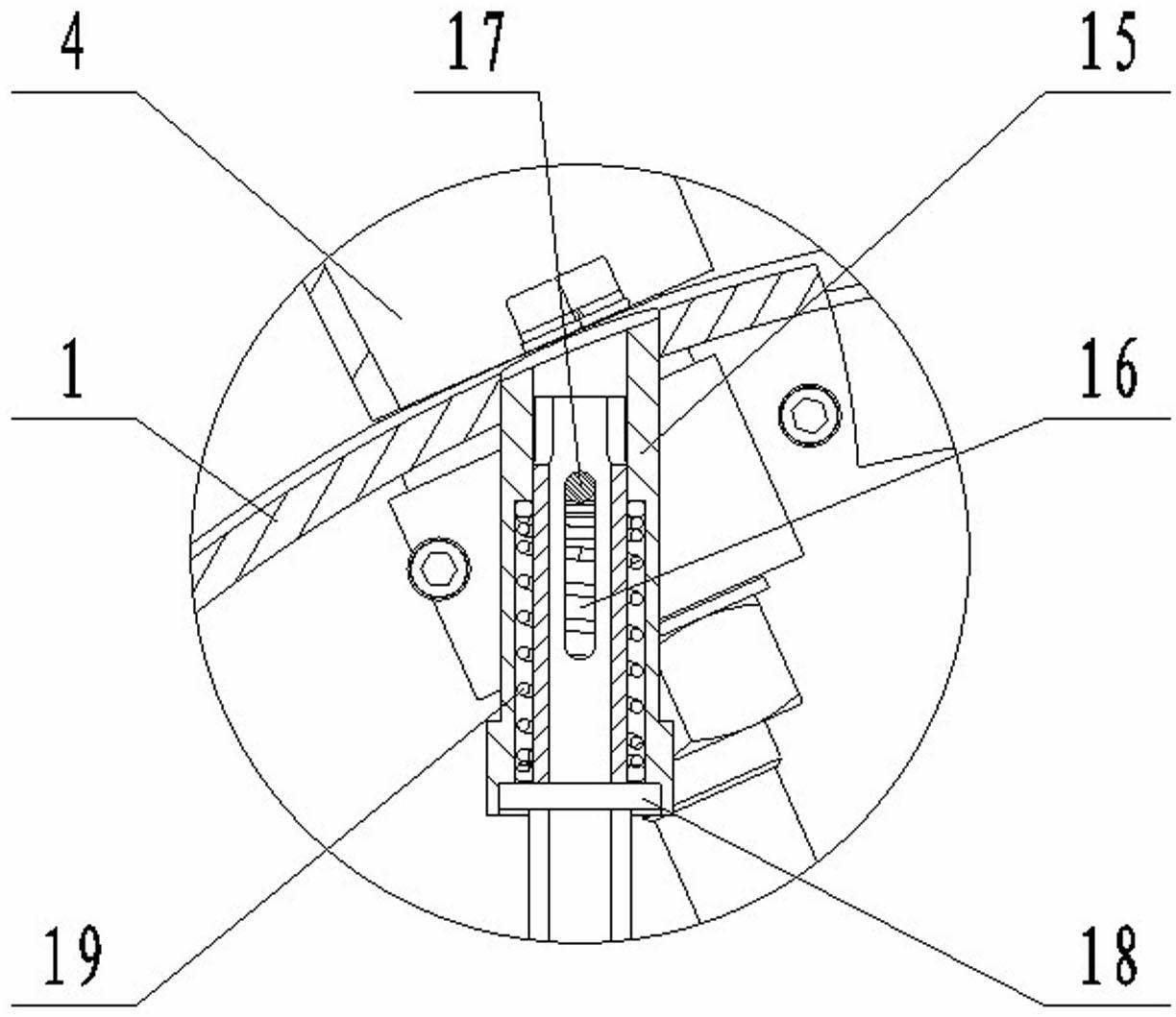
[0014] The blade synchronously adjusts the axial flow fan, including the hub 1 and the shaft sleeve 2 coaxial with it, the hub 1 is pierced with a number of radially arranged petioles 3, the outer ends of the petioles 3 are fixed with blades 4, and the shaft sleeve 2 is covered with left and right The push plate 5 that slides on it and protrudes from the middle part of the right end face has a circumferential groove 6 on the outer cylindrical surface of the push plate 5, and a crank 7 whose other end is hinged with the petiole 3 is placed in the groove 6, and the right end of the push plate 5 is The side is provided with a worm wheel 8 sleeved on the shaft sleeve 2, the inner hole of the worm wheel 8 is threaded with the outer cylindrical surface protruding from the middle part of the right end face of the push plate 5, and the outside of the left and right end faces of the worm wheel 8 is provided with a support seat 9 fixed with the shaft sleeve 2 and Cover plate 10, worm sup...


PUM


Abstract

The invention particularly discloses an axial flow ventilator capable of synchronously adjusting blades, and is used for solving the problems of time waste and labor waste during adjustment of mounting angles of the blades of the conventional axial flow ventilator and the problem of influence of unbalance of a blade wheel on the service life of the conventional axial flow ventilator. A push disk is sleeved on a shaft sleeve; a groove is formed on the outer cylindrical surface of the push disk; a crank is arranged in the groove; a worm wheel which is in threaded connection with the push disk is arranged on the right side of the push disk; a supporting seat and a cover plate are arranged on the outer sides of the left end face and the right end face of the worm wheel; a worm support is fixed on the supporting seat; a worm is inserted into the worm support; a balance weight rod is arranged on the other side of the worm; a driving rod is fixed at one end of the worm; the outer end of the driving rod is positioned in a supporting sleeve; a clamping slot is formed on the stair surface of the supporting sleeve; a pin shaft is inserted into a sliding chute hole of the driving rod; a sealing gasket is sleeved on the driving rod; and a spring is arranged between the sealing gasket and the pin shaft. According to the axial flow ventilator, the efficiency of adjusting the mounting angles of the blades is improved, and the consistency of the mounting angles is guaranteed; and the axial flow ventilator has the advantages of simple structure, low cost and convenience in maintenance, and is easy to mount.

Description

technical field [0001] The invention relates to an axial flow fan, in particular to an axial flow fan with synchronous adjustment of blades. Background technique [0002] As the main mine fan, the axial flow fan is known as the coal mine throat equipment, and its service life is generally more than 10 years; the mine resistance parameters and the mine air volume may change at any time during use, which requires adjusting the installation angle of the main fan blades to meet mine needs. [0003] At present, the blade adjustment method of the mine main ventilator mainly adopts the method of shutting down and disassembling the machine and adjusting the blades one by one. The adjustment process is as follows: first disassemble the fan from the impeller section, and then use a special wrench to loosen the lock nut and the conical nut in turn. Rotate the blades, and tighten the conical nuts and lock nuts in sequence to the required angle. Because the operating environment of the ...

Claims


Application Information

Patent Timeline
Patent Type & Authority Applications(China)
IPC IPC(8): F04D29/36
Inventor 向毅张始斋董明洪李俊罗松袁小平黄学满卢芳任华雄吴喜文樊晨洁张登峰梁小龙薛佳佳李文晶尉彦国
Owner 山西渝煤科安运风机有限公司
Why Eureka
Try Eureka